Welcome to Laser Pointer Forums - discuss green laser pointers, blue laser pointers, and all types of lasers

LPF Donation via Stripe | LPF Donation - Other Methods

Links below open in new window

ArcticMyst Security by Avery

Help wanted developing idea for a all in one driver test bed

Joined
Oct 3, 2011
Messages
899
Points
0
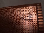
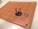
One of the biggest things I fret over when building my handhelds is setting up my drivers. Soldering wires to the driver just to be able to connect it to a battery or power source and driver dummy load is a real PITA. Un- soldering them and then cleaning the holes to accept new wire is also a PITA. I came up with a solution to this that has worked well so far. I think it's something that could be taken one step further and marketed to builders here. Basically all I did was take some solid silver wire (silver because I had it and it was the exact diameter of the holes in the drivers) and runn it through a PCB proto board in such a way that I can slip the driver down over the wires and connect my leads to my dummy load and PS? It works really well, very quick and simple solution to a problem that has given me much angst over the years.

What I envision is a single PCB with several slots where these "test prongs" are available to accept the most common drivers we use (X-drive, Flexdrives, Lava, mohgashm, etc) Additional there could be one or two "general purpose" slots with malleable prongs spaced in some general dimensions to accept drivers that are not the common ones. All of the prongs would have traces leading to common input and output terminals you could easily connect your PS and dummy load to. I also imagine going even a step further and including the dummy load and even a battery cage for one or two 3.7v cells on the board.

I have included some pics of my simplified prototype below. My hopes are that someone with the knowledge and skill to help me develop the PCB will step up and give me a hand with this. I will front the $$$ to get something like this produced if someone would be willing to help me. I'm not trying to make any profit on the forum, just bring something useful to the members. I suppose if someone were to help me and there was the need for them to get a little kickback on this we could discuss it. That's not really my interests but if it's the only way then we can talk. I was thinking a basic board with prongs should run somewhere around $10? Maybe less., that's my hopes anyways. I could be very niaeve to the costs of producing something like this, but based in some of the items I've seen around here that seems well within the ballpark. Something with a built in dummy load and battery cage might be $30-40? Not sure.

PM me if you can help or if you have general suggestions.
Jmillerdoc
 

Attachments

  • image.jpg
    image.jpg
    32.5 KB · Views: 169
Last edited:


Joined
Feb 18, 2013
Messages
744
Points
28
Awesome! I am also not fond of soldering/de soldering drivers, especially microboost...

Thanks and +rep
 
Joined
Oct 3, 2011
Messages
899
Points
0
I've sent a message to a couple members here that I know have some experience with this sort of thing. Flamingpyro is one. I'm going to make this a priority on my hobby priority list. Even if I have to figure out how to do it by myself. I think the hardest part is setting up the PCB using some sort of software. Then it will be finding the most economical way to have the boards made. I've also asked Lazeerer to chime in. I know these guys have this stuff made all the time. Just a matter of connecting the right minds with the most cost effective resources. It will happen. DTR- I've got you down for a beta when I finally get this done.
 

Zeebit

0
Joined
Aug 27, 2012
Messages
1,110
Points
0
I am sorry but never heard of a pogo pin. Will you elaborate?

Its a spring loaded connector. There are some variations but here's an example:

6678.jpg
 
Joined
Feb 26, 2014
Messages
231
Points
18
I made a quick PCB sketch with Fritzing (circuit design software + fabrication service). This board is made to hold either a Microboost or an X-drive. Of course, the dimensions on this aren't exact (especially the driver pin spacing) but this is just a rough draft. If anyone can get me the exact pin-spacing measurements for the X-drive and the Microboost I can adjust it to get it right.

Screen_Shot_2014_04_28_at_12_36_12_PM.png


The way it works is that there is a battery input in the bottom right (labeled "Power"). Here you solder the leads from a battery holder. There are traces on the bottom of the board (orange in this sketch) that will connect the battery holder to the +/- driver inputs.

Once your batteries are in, you can put one driver (NOT two) into it's holder. The holders would be made up of 4 pins (probably pogo pins, but possibly just wire) that line up with the holes on the driver so you can just slide them on.

Then the battery power travels to the driver inputs, and you have driver output pads on the opposite side of the board. You can then connect these to a test load.
If enough people are interested, we may be able to have a built-in test load like Jeff suggested. This would drive up the cost of the board though due to a larger board and more components. Alternatively, we could have a diode testing socket on the end so you could power the diode and LPM it to see the output. (Diode testing socket like this one)
Heck, we could even have a test load AND a diode socket on the board with some way to switch from the test load to the socket.

The price to fabricate 10 of these boards (without components) would be $13.31 each. Qty 5 would be $16.63 each; A single board would be $23.29. If anyone wants the price for a board with components or a board with a built-in test load let me know and I'll throw one together.

Just some thoughts :yh: Suggestions are welcome!
 
Joined
Oct 3, 2011
Messages
899
Points
0
Its a spring loaded connector. There are some variations but here's an example:

6678.jpg

Google this and found a bunch of them online. I just bought 100 of them at deal extreme for about eight dollars. I'm going to build a more elaborate prototype and see how it works. What is for somebody to loan me one of all of the major players in drivers so I can map the pinholes out. Hint hint for anybody watching this..... I've got a few currently but probably need about five or six others as well
 

sinner

0
Joined
Oct 27, 2011
Messages
2,565
Points
83
It is an excellent idea, these pins should help in making good connections too, With the boost drivers you can't risk loose connections at all.
 
Joined
Feb 26, 2014
Messages
231
Points
18
Adding to my last post (#9):

I added a spot for a 17mm round driver on the board. The outer ring is connected to the negative from the battery and the -out pad; the inner pad is connected to the positive from the battery and the +out pad.

The orange traces are the bottom of the board, the yellow traces are the top of the board, and the blue trace is a jumper wire.

Screen_Shot_2014_04_28_at_2_42_54_PM.png


Edit: These would be $19.93 each w/o components for a batch of 10.

Any comments or suggestions or anything?
 
Last edited:
Joined
Oct 3, 2011
Messages
899
Points
0
@Adam- looks like you know what you're doing here. Here is what I propose: let's do it with a built in test dummy load and a socket for the different pin outs for each of the LED's we commonly use. I've got some diode test sockets the LD will plug into, we can put a small switch on the board to switch between the two. For the test load diodes we can use the round 10a versions I upgraded my board to recently, they will easily handle 2-3a for 30-45 sec. No battery cage. Just a test board with dummy and sockets for LD's included. I will talk with Lazeerer and DTR about getting some common drivers to measure the pin spacing. We can make a poll on which drivers to include, maybe 6-8 different driver types and one slot with insulated wires about an inch long with 1/8" stripped off the ends to sever as a catch all slot. If we can get this traced out and ready to send to the PCB manufacturer I will front the cost for at least ten of these. For those helping materially with the effort I will give them one or two for helping. The rest I will sell for cost to the forum and if there is enough interest we can build more. I don't really have the time or desire to run a web store for these so if you wanted to sell them that would be fine. Alternately, maybe DTR or someone already running a webstore could sell them. I'm open minded. I just want to see this made. Let me know what you think.
 
Joined
Oct 3, 2011
Messages
899
Points
0
We could even offer two options of build quality/capacity. One with lower rated diodes and one upgraded Naked Z-foil ultra precision test resistor (0.1% or better variance from 1R). These Z-foil resistors are not cheap ($10 or so) but well worth the precision IMHO. Having the ability to accurately measure your current is key when running on close tolerances on some of these diodes we use (405). Having a 5-10% tolerance test resistor can lead to way to much variability in your measurement. Up to 100-200mA off in some cases. Again, I will front the $$$ to get several of these built for the first go around.
 
Joined
Oct 3, 2011
Messages
899
Points
0
Here is the resistor I use....Nude not naked, 0.25% tolerance
 

Attachments

  • image.jpg
    image.jpg
    179.2 KB · Views: 155
Joined
Feb 26, 2014
Messages
231
Points
18
I like your suggestions Jeff!
Offering 2 builds sounds like a good plan; some people don't need to be exactly accurate while others I'm sure want the laser to be perfect.
I'll follow the schematic from some common test loads and add that to the board when I get home later & upload it here. I'll also add the catch-all slot and leave room for more drivers so that we can get a price with the bigger board.
Where did you get your test sockets? I can't find anything but 5.6mm and those are $14 each which is a bit ridiculous for this application.
 
Last edited:


Top