Welcome to Laser Pointer Forums - discuss green laser pointers, blue laser pointers, and all types of lasers

LPF Donation via Stripe | LPF Donation - Other Methods

Links below open in new window

ArcticMyst Security by Avery

FREE DIY open source BOOST driver!!! Tested & working!!

Joined
Mar 29, 2011
Messages
1,056
Points
48
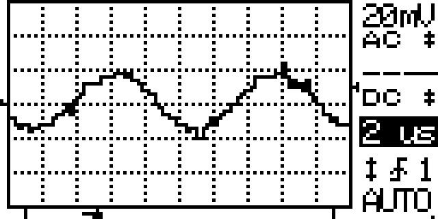
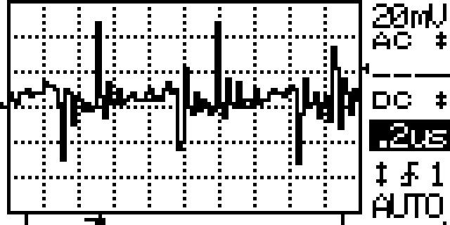
Well then it does sound like its best to remove it. I wonder if it would be possible to get the better ripple but no oscillations by putting a small cap between FB and ground instead of between LD+/-?

I tried that also.. No change at all as if it weren't there. I tried 0.1uF and 2.2uF.. Same output.


Joined
Mar 29, 2011
Messages
1,056
Points
48
I tried adding caps to that lasever driver and saw no change either. I'm starting to think we have been over thinking or overemphasizing caps for ripple control, but if not caps - what?

http://laserpointerforums.com/f67/switching-driver-445nm-405nm-75301-2.html#post1093772

I think we need a resistor and a cap in series. Paralleled to either Vout and FB or FB and ground.... But at what values is a total mistery to me :D..

I also tried adding more than 200uF at the output on my driver and there wasn't any change at all :D

and btw does somebody knows what kizdawg posted a few posts back? o_O I can't seem to figure it out.. :D
 
Last edited:

benmwv

0
Joined
Sep 10, 2010
Messages
1,380
Points
48
Its a picture of a 9mm diode running at 2.9A producing 3.5W. Poor little diode!
 

rhd

0
Joined
Dec 7, 2010
Messages
8,475
Points
0
You could potentially use another inductor to create a PI filter, if the ripple is really driving you nuts.
 
Joined
Mar 29, 2011
Messages
1,056
Points
48
You could potentially use another inductor to create a PI filter, if the ripple is really driving you nuts.

that sounds good but isn't the inductor supposed to be able to carry the output current. that will result in larger inductor and will take a lot of space :? or am I wrong :thinking:
 

rhd

0
Joined
Dec 7, 2010
Messages
8,475
Points
0
I would think that you could actually use an inductor that was rated for less current than the main inductor, because you'd only need it to handle less than, say, 1.4A with a Ben boost.

I'm actually not sure how to select inductance when building a PI filter. I would probably look for the lowest resistance from an inductor of 5 to 10 uH, and capable of maybe 1.5A+, in a small shielded package.
 
Joined
Mar 29, 2011
Messages
1,056
Points
48
I would think that you could actually use an inductor that was rated for less current than the main inductor, because you'd only need it to handle less than, say, 1.4A with a Ben boost.

I'm actually not sure how to select inductance when building a PI filter. I would probably look for the lowest resistance from an inductor of 5 to 10 uH, and capable of maybe 1.5A+, in a small shielded package.


Chebyshev Pi LC Low Pass Filter Calculator

here is a PI calculator, somebody can figure it out maybe? :thinking: :D
 
Joined
Feb 7, 2012
Messages
977
Points
0
I wish I could help with this but I am stuck just reading it all. I just dont have enough experience or knowledge on this to help out. And yes that was my poor little diode.. dead diode now. No surprise there.. Someone even called me a 'Serial Diode Killer'... It died at 3150ma I really want intending on going that high but eh it happened it definately went through all the torture testing I could give it.
 

Blord

0
Joined
Dec 24, 2007
Messages
5,356
Points
0
I have build a triple Ben boostdriver with R200, R280 and R280 as set resistors. The LM340 is heatsinked with copper plates onto the aluminum pill.
The output of the combined drivers is 2.2A. I measured it directly between the 9mm diode and the driver with a Fluke DMM.
The output is stable during 1 min test but it fluctuates a little. I believe +/- 10mA. Not so rockstable as a buck driver.
At least it is stable than two Ben driver at the same 2.2A setup. With two drivers the output drops very much after 10-15sec no matter how good the heatsinks are.

More numbers : Vf diode was 4.8V, battery input of 3x 18650 Sanyo 18650 batteries are 3.7A/4.0V
I calculate an efficiency of (2.2x4.8)/(3.7x4.0)= 71.4%

Is that in line with the expectation of this driver ?

CQG-35.jpg
 

benmwv

0
Joined
Sep 10, 2010
Messages
1,380
Points
48
Im surprised that the 2 drivers couldn't handle it. I still think it must be because of the poor heatsinking ability of the sot23-5 package. The input current is only 3.7A and two drivers should be able to handle about 6A. Hopefully the DFN version will have good enough heatsinking to utilize the full switch current without overheating.

70% is a bit on the low side but I guess since you are using three drivers in parallel the efficiency will be lower.
 

Blord

0
Joined
Dec 24, 2007
Messages
5,356
Points
0
I think the 4.0V of the batteries aren't correct. I need to remeasure it.
4V is the voltage of unloaded batteries :)

***edit***

I measure 3.74V under load so the calculation is (2.2x4.8)/(3.7x3.74)= 76.3% !
Much better now.
 
Last edited:

benmwv

0
Joined
Sep 10, 2010
Messages
1,380
Points
48
Well if it is actually lower than 4v your efficiency figure will increase.
 
Joined
Mar 29, 2011
Messages
1,056
Points
48
ok I did my tests on video and pictures this time instead of just my word for it. :D

I made two identical setups of the ben boost but on first tests we have 22uF cap between LD+ and LD- (Vout and FB)

on the second test we don't have that cap.

Input and Output caps are both 22uF on both tests.
Output current is set to ~1.25A approximately.

P1070092.jpg

P1070093.jpg


check the videos too.

the problem can be seen pretty clearly on the 1st video with the 22uF cap.
It is causing oscillations at larger input / output voltage difference.

When the difference is 0.3V no oscillations. But that's not what we need right :D..
The output ripple looks better though only 20mA!

The driver without cap is keeping a relatively steady ripple of 60 to 80mA in all voltage ranges. I would prefer this than the oscillations.

and btw 60mA is the overall ripple what the diodes sees above the average current is just half of that so 30mA.. That's pretty good in my opinion for a boost driver. Buck drivers tend to be far more gentle on the ripples. Actually the Cree Buck driver from DX that is $2 is actually having only 10mA of output current ripple.. that's just awesome. :D

If you have any requests on testing drivers on scope or more tests on the ben boost let me know.

Oh about the thermal shutdown people tend to have ...
You might have noticed that the Inductor gets pretty hot after few seconds even when the IC is heatsinked. I am thinking this could cause the thermal shutdown too. Maybe you should heatsink both sides of the driver.


oh about startup spikes both have good startups with 22uF caps on input and output:


22uF Vout/FB cap startup
benboost22uFcapstartup.jpg


no Vout/FB cap startup
benboostnocapstartup.jpg


22uF Vout/FB cap ripple and oscillations
benboost22uFcaposcillationsripple.jpg


no Vout/FB cap ripple
benboostnocapripple.jpg
 
Last edited:

rhd

0
Joined
Dec 7, 2010
Messages
8,475
Points
0
Using this calculator:
Pronine Electronics Design - Butterworth Pi Low Pass Filter Calculator

My approach to calculations:

Cutoff Frequency (FC): We want to filter out 1.6 Mhz ripple. It's a low-pass filter, so I decided on 1Mhz (everything above that should be filtered out).
Characteristic Impedance (Zo): Voltage / Current, which is going to be roughly 4.
Number of Components: We're talking about a Cap-Inductor-Cap PI filter, so that's 3 components to the chain.

These figures basically imply 0.04 uF caps, and a 1.27 uF inductor. An appropriate Inductor might be something like this:
IHLP1212BZER1R5M11 Vishay Dale | 541-1321-1-ND | DigiKey
It's 1.5 uF, can easily handle our current levels, has relatively low resistance (so it won't waste much power), and it's small, at 3.6 x 3.0 mm. It's also cheap ($1.30 in single QTYs).

Similarly, a couple caps of that nature should be relatively inexpensive:
08055C473JAT2A AVX Corporation | 478-3771-1-ND | DigiKey

I might have made a mistake - so don't bank on my numbers. I'm also not sure this will work, never having implemented this filter before.
 
Joined
Sep 20, 2008
Messages
17,622
Points
113
Using this calculator:
Pronine Electronics Design - Butterworth Pi Low Pass Filter Calculator

My approach to calculations:

Cutoff Frequency (FC): We want to filter out 1.6 Mhz ripple. It's a low-pass filter, so I decided on 1Mhz (everything above that should be filtered out).
Characteristic Impedance (Zo): Voltage / Current, which is going to be roughly 4.
Number of Components: We're talking about a Cap-Inductor-Cap PI filter, so that's 3 components to the chain.

These figures basically imply 0.04 uF caps, and a 1.27 uF inductor. An appropriate Inductor might be something like this:
IHLP1212BZER1R5M11 Vishay Dale | 541-1321-1-ND | DigiKey
It's 1.5 uF, can easily handle our current levels, has relatively low resistance (so it won't waste much power), and it's small, at 3.6 x 3.0 mm. It's also cheap ($1.30 in single QTYs).

Similarly, a couple caps of that nature should be relatively inexpensive:
08055C473JAT2A AVX Corporation | 478-3771-1-ND | DigiKey

I might have made a mistake - so don't bank on my numbers. I'm also not sure this will work, never having implemented this filter before.

Just a friendly heads up...
Inductors are measured in Henrys... (uH in this case)
Capacitors are measured in Farads... :beer:


Jerry


Top