Welcome to Laser Pointer Forums - discuss green laser pointers, blue laser pointers, and all types of lasers

LPF Donation via Stripe | LPF Donation - Other Methods

Links below open in new window

ArcticMyst Security by Avery

Does it matter which end of a test load the resistor goes?

Joined
May 26, 2008
Messages
185
Points
18
Hi guys.

A little confused here.

I've just built my first test load based on these two schematics,
testload01.jpg

dummyload.jpg


then came across this other diagram that seems to contradict it in terms of the position of the 1R resistor,
DDLcircuittest01.jpg


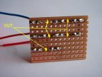
and here's a picture of my own. The blue wire is negative, and the two reds are positive, for red and blue LD testing.
P9240001.jpg


I've checked a few other posts and found no mention of the difference and whether it means anything.

Am I missing something here, and need to reposition my resistor and connector leads?

Thanks for any help.


Morgan

0
Joined
Feb 5, 2009
Messages
2,174
Points
0
In short, no...

Current flows through it wherever it comes in the circuit.

M
:)
 
Joined
May 26, 2008
Messages
185
Points
18
Thank you sir.

:)

Incidentally, are diodes easy to kill with too much heat from soldering? I think I maintained contact with iron set to hot for up to 5-6 seconds for each joint.

I've plugged this into a bread-board driver I've made that works whenever my test module is plugged into it, and I read no mV across the resistor at all; I understand that I'm supposed to measure for mV across the 1R resistor, and that directly translates into mA.

Can anyone spot anything I may have missed?

Here's a picture of the reverse side too. If you look closely you can still see the resistor, and diodes in the holes between the joints, and also where the wires join (blue=negative, red=positive).
P9240001b.jpg
 

Benm

0
Joined
Aug 16, 2007
Messages
7,896
Points
113
Err... those are conducting lanes on that board, not solder islands. You are shorting out several of the diodes this way. Remove any copper that is underneath each diode (easily doable with a drill bit by hand).
 

Toke

0
Joined
Jul 25, 2010
Messages
1,099
Points
0
I see your problem. :D

The print board is amde with cobber lanes instead of islands, that means that everything on the same lane is shorted.
In this case you have both ends of the resistor on the same lane, and it is perfectly natural to measure nothing as the current is going through the lane below the resistor.

Your test load is currently one or two diodes depending on wire used.
It can be fixed by scraping/cutting through the lanes at each component.

ETA:
Benm, You are not supposed to post while I am typing.
 
Joined
Sep 20, 2008
Messages
17,622
Points
113
You will need to cut the traces as shown in the attached
drawing...

You need to remove the short on each of individual diode...:cool:

BTW... there are only 2 diodes connected correctly in your original
photo.. (the vertical ones in the 1st photo..)


Jerry
 

Attachments

  • PCB TL.jpg
    PCB TL.jpg
    45.4 KB · Views: 408
Last edited:
Joined
May 26, 2008
Messages
185
Points
18
Guys, thank you :)

If I knew the how to do the facepalm thing, I'd do it now.

Made the cuts, plugged it back into the breadboard DDL, AND IT WORKS!!

P9240001c.jpg


Lesson learned ;)

I'll make another one, properly next time, and a bit neater too.


Thanks again.
 
Joined
Sep 20, 2008
Messages
17,622
Points
113
That one looks neater than some I've seen posted
on the Forum... and your solder joints are well done.

Jerry
 
Joined
May 26, 2008
Messages
185
Points
18
Cheers Jerry, too kind ;)

Well, I steamed ahead, transferred all the parts from the breadboard to a small PCB, tested the driver with the new test load, mounted my red 650nm "Rohm" LD into a module, soldered that, wired and put it all together in a project box.

I took pics of the process as it's my first ever build from scratch, and will post a new thread detailing it all tonight, or over the weekend for sure.

Thanks again guys, for the help today, and until now of course.

I'm not the most patient person, and would likely have pressed ahead without testing the driver, and broken something.
 
Last edited:

Toke

0
Joined
Jul 25, 2010
Messages
1,099
Points
0
Congratulations, that first light on the wall from first working diode looks remarkably good. :)
 
Joined
Jun 24, 2010
Messages
243
Points
18
Thank you sir.

:)

Incidentally, are diodes easy to kill with too much heat from soldering? I think I maintained contact with iron set to hot for up to 5-6 seconds for each joint.


It's possible, but they're pretty robust. I did a test once with a generic 1A silicon rectifier diode and cooked it on a hot plate at 500F for over an hour, at which point it still worked fine. I wrapped it to the end of a soldering iron tip and ran it up to 700F at which point measured leakage went up a bit but upon cooling it was fine. I finally tried heating it with a flame until the plastic casing caught fire, it would go leaky but then recover once it cooled. After several cycles from smoking back down to ambient it went open circuit. I'm assuming thermal cycling cracked the die or broke the bond wire.

You still want to avoid unnecessary heating, but many semiconductors are pretty durable.
 
Joined
May 26, 2008
Messages
185
Points
18
Congratulations, that first light on the wall from first working diode looks remarkably good.

Yeah Toke, talk about grinning from ear to ear!

I can see this getting totally addictive now though, as I'll be all over the optics section trying to figure out why I get so much, glow around the dot. I assume it's reflection due to a poor quality lens, and will explain better with pictures when I post it all properly.

It's possible, but they're pretty robust. I did a test once with a generic 1A silicon rectifier diode and cooked it on a hot plate at 500F for over an hour, at which point it still worked fine. I wrapped it to the end of a soldering iron tip and ran it up to 700F at which point measured leakage went up a bit but upon cooling it was fine. I finally tried heating it with a flame until the plastic casing caught fire, it would go leaky but then recover once it cooled. After several cycles from smoking back down to ambient it went open circuit. I'm assuming thermal cycling cracked the die or broke the bond wire.

You still want to avoid unnecessary heating, but many semiconductors are pretty durable.

Thanks. Given your tests they seem almost in-destructible. I read somewhere to use the iron as hot as I can get it, and solder as fast as possible with minimal contact. Seems ok so far as nothing's died yet.

I mistakenly thought I might have killed a diode before even considering I might have made a schoolboy error in the PCB layout. :)
 
Joined
Jun 24, 2010
Messages
243
Points
18
No, you don't want the iron as hot as you can get it, that will burn the flux and damage the PCB, not to mention the thermal stress can damage components. You want to use about 700F for regular tin/lead solder, perhaps 750-800F for the lead free crap. Soldering properly takes practice but once you get the hang of it it's second nature. I recommend a temperature controlled soldering iron for all but the most basic work. They cost a bit more than a Radio Shack iron but it's cheaper than killing expensive parts.
 
Joined
May 26, 2008
Messages
185
Points
18
Fair enough, cheers for the heads-up.

Mine aspires to "temperature controlled" status, it's an adjustable iron in that it has a dial to turn up the heat, but no temperature output. Just an increasing colour scale from yellow to red. Precision kit!! ;)

Any reason to buy a new gadget is a good thing though :)
 

Morgan

0
Joined
Feb 5, 2009
Messages
2,174
Points
0
Your soldering did look very neat as Jerry said. I personally would stick with it until you encounter a problem. Nice and shiny!

Just for future reference, here's a face palm for you...

... (but not a cruel one as you don't deserve it! It's a face... cut into a palm! ;) )

14bknpt.jpg


Can you edit one of your posts in this thread to add a link to the successful build please?

M
:)
 
Last edited:
Joined
May 26, 2008
Messages
185
Points
18
Your soldering did look very neat as Jerry said. I personally would stick with it until you encounter a problem. Nice and shiny!

Just for future reference, here's a face palm for you...

... (but not a cruel one as you don't deserve it! It's a face... cut into a palm! ;) )

14bknpt.jpg


Can you edit one of your posts in this thread to add a link to the successful build please?

M
:)

hahaha, nice!

Thanks Morgan.

Here's a link to the successful first build. If there's a better/preferred way to link to it, please mention.

http://laserpointerforums.com/f50/my-first-build-beginner-beginners-56055.html

Again, thanks for all your help everyone. I really appreciate it :) .


Top