Welcome to Laser Pointer Forums - discuss green laser pointers, blue laser pointers, and all types of lasers

LPF Donation via Stripe | LPF Donation - Other Methods

Links below open in new window

ArcticMyst Security by Avery

Diy driver output seems low

Joined
Dec 17, 2016
Messages
7
Points
0
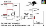
I built my own driver so I can play around with a bunch of diodes I hacked out of lightscribe drives. I have a flat package 790? (Near ir at least) with a standard glass aixiz lens and an open can red with a g2, both smoking an old shoe over 10 feet away. Pretty awesome for a n00b imo, but when I had everything hooked to my test circuit I couldn't get my driver much higher than (an estimated) 250mA. My dmm stops at 200mA before I have to switch the cable and range but I got skittish after I led'd a good can trying to switch it while it was running. :durr: Anyhow, my setup is as follows:
lm317t
5ohm 1/2 or 3/4 watt resistor
1k 15 turn pot (all I could find at radio shack)
4001 diode
16v 47 uf cap.
Power source is an eflite 7.4v 800 mAh lipo

From what I've read this setup SHOULD be outputting up to 500mA. I do plan on picking up a 100 ohm pot (or twelve) and im waiting on a couple chinese noname drivers but I plan on running a similar circuit to this on the engraver I'm building so I'd like to figure out what I'm doing wrong.
 

Attachments

  • 20161213_123808-800x600.jpg
    20161213_123808-800x600.jpg
    174 KB · Views: 97
Last edited:


diachi

0
Joined
Feb 22, 2008
Messages
9,700
Points
113
Do you have a diagram showing how you have everything connected? How/where are you measuring current? Is the 4001 your "load" so to speak?

Using a 5ohm for current set on an LM317 constant current circuit will give you 250mA.
 
Last edited:
Joined
Dec 17, 2016
Messages
7
Points
0
The test load components were 4 4007 diodes in series and two half ohm resistors series. All the components listed in the first post were just the driver. I set it up based on the attached pic. But if youre saying a 5 ohm resistor as the current set will give me 250mA then I'll play around with less resistance.
 

Attachments

  • JWUc0Qz-800x500.jpeg
    JWUc0Qz-800x500.jpeg
    70.3 KB · Views: 77

diachi

0
Joined
Feb 22, 2008
Messages
9,700
Points
113
The test load components were 4 4007 diodes in series and two half ohm resistors series. All the components listed in the first post were just the driver. I set it up based on the attached pic. But if youre saying a 5 ohm resistor as the current set will give me 250mA then I'll play around with less resistance.


Yes, replacing the 5ohm for a 2.5ohm will allow 500mA.

Take into consideration any extra power dissipation when running at higher currents of course.
 
Last edited:
Joined
Dec 17, 2016
Messages
7
Points
0
Thanks! I'll have to mess with it when I get home from work tonight. I dont plan on pushing them (at least the red) too hard but i want to at least be able to get close.
 

diachi

0
Joined
Feb 22, 2008
Messages
9,700
Points
113
Thanks! I'll have to mess with it when I get home from work tonight. I dont plan on pushing them (at least the red) too hard but i want to at least be able to get close.


I wouldn't push them too much past 250mA to be fair...
 
Joined
Dec 17, 2016
Messages
7
Points
0
Good point. I'm sure the red will handle quite a bit more. I've read about folks here pushing them up to 450. But I'm not trying to kill it before I put it in my host so I wont give it too much.
I've also looked at the datasheets on the flat ir and its about maxed already. If I go any higher with it it will need a pulsed driver. I'll more than likely be running 2 of these through a beam splitter for more reliability and power but that's another subject all together.
 

Benm

0
Joined
Aug 16, 2007
Messages
7,896
Points
113
5 ohm would provide 250 mA at best indeed, so that's actually correct.

If you use a setup like this, you can also measure the current by measuring the voltage over the fixed resistor (not the potmeter, just the fixed one) and calculating current from that.

This requires some calculation (like diving by 2 in case of a 2 ohm resistor) but has the benefit of not having to stick the current meter in series. This solves problems with dodgy connections, having to switch wires to a higher range and all that, and also eliminates voltage loss over the multimeter which can be considerable when maxing out the 200/400 mA range for example.


Top