- Joined
- Apr 4, 2016
- Messages
- 3
- Points
- 0
Hello Everyone,
I've been researching the DDL laser driver and would like some help in understanding the circuit. I intent to use it to build a 690nm laser with a 10mW output (I'd like to start small and happen to have this diode around), preferably using 5 volts. I figured I'd start by stating what I do understand before going onto my question. If I'm posting this in the wrong forum I apologize. I'm new here and the amount of content is overwhelming.
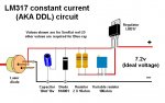
Concerning the components of the DDL circuit attached below, I understand that:
-The diode is to protect the laser diode in case the batteries are placed in reverse
-The Capacitor is to smooth out the current going into the laser diode
-The potentiometer is to adjust the resistance of the system ( the greater the resistance, the less the current).
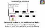
Additionally, I understand that you can test the current output by using a dummy load instead of the laser driver if you do not want to burn it (other picture). the diodes are chosen to have a voltage drop close or at the operating voltage of the laser diode. The 1-ohm resistor is to use Ohm's law to figure out the current flowing thru it.
My questions are:
-Is there a calculation for determining the capacitance to use?
-Why do we have fixed resistors if we have a potentiometer?
-How do we calculate the fixed resistor values?
-When choosing a voltage to supply to the LM317, is it 3V + Operating voltage of the laser driver? I'm not sure why 3V, but from what I can understand the LM317 requires 3V.
Again, I apologize if I've done something wrong and thank you for your time.
I've been researching the DDL laser driver and would like some help in understanding the circuit. I intent to use it to build a 690nm laser with a 10mW output (I'd like to start small and happen to have this diode around), preferably using 5 volts. I figured I'd start by stating what I do understand before going onto my question. If I'm posting this in the wrong forum I apologize. I'm new here and the amount of content is overwhelming.
Concerning the components of the DDL circuit attached below, I understand that:
-The diode is to protect the laser diode in case the batteries are placed in reverse
-The Capacitor is to smooth out the current going into the laser diode
-The potentiometer is to adjust the resistance of the system ( the greater the resistance, the less the current).
Additionally, I understand that you can test the current output by using a dummy load instead of the laser driver if you do not want to burn it (other picture). the diodes are chosen to have a voltage drop close or at the operating voltage of the laser diode. The 1-ohm resistor is to use Ohm's law to figure out the current flowing thru it.
My questions are:
-Is there a calculation for determining the capacitance to use?
-Why do we have fixed resistors if we have a potentiometer?
-How do we calculate the fixed resistor values?
-When choosing a voltage to supply to the LM317, is it 3V + Operating voltage of the laser driver? I'm not sure why 3V, but from what I can understand the LM317 requires 3V.
Again, I apologize if I've done something wrong and thank you for your time.