Welcome to Laser Pointer Forums - discuss green laser pointers, blue laser pointers, and all types of lasers

LPF Donation via Stripe | LPF Donation - Other Methods

Links below open in new window

ArcticMyst Security by Avery

Circuit to control laser diode by an Arduino

alan

0
Joined
Aug 3, 2011
Messages
7
Points
0
Hey all,

I've been lurking for a few weeks but this is my first post so go easy on me :)

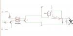
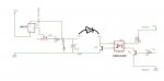
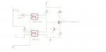
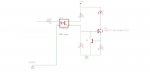
I'd like to use an Arduino (uno) and an optocoupler to TTL/PWM switch a ir LD (808 nm, 280 mA) which gets a constant current from an LM317. From my lurking here (thanks folks for all the excellent info) and in an effort to learn a little bit of eagle I've drawn up the following two circuits (which I hope upload ok!).

In both circuits the arduino drives the opto via transistor 1. In the first circuit (LD on the right) the opto then switches the supply to the LM317 via transistor 2. In the second circuit (LD in the middle) the opto switches the current through the LD via transistor 2.

I'm not an electronics engineer so I'm wondering which (if any) of these approaches makes (most) sense? Or am I going to kill the LM317 or LD...?

All the best,

Alan.
 

Attachments

  • laser ddl1.jpg
    laser ddl1.jpg
    19.7 KB · Views: 18,190
  • laser ddl2.jpg
    laser ddl2.jpg
    20 KB · Views: 11,685


Joined
Jun 12, 2011
Messages
292
Points
0
Thats a LOT of work to control a laser when you could just use a RC DAC + a npn transistor, to control current.
 
Joined
Oct 26, 2007
Messages
5,438
Points
83
Just forego the LM317 and control a transistor directly. You can rig something like this up, only with a laser instead of LED.
 

alan

0
Joined
Aug 3, 2011
Messages
7
Points
0
Thanks for all the replies.

Bionic-Badger, I've been looking at that instructables circuit you linked to and I have a real newbie question for anyone with patience/time....
If I have 5V VCC, a 2.2V LD operating voltage and a 0.28A operating current.... is the following correct?
R3 = (5V-2.2V)/0.28A = 2.8V/0.28A = 10 Ohms
with a power dissipation of 0.28A*2.8V = 0.784 W
Or am I omitting something? There isn't a 0.7V drop across the Q2 NFET by any chance?

Cheers,

Alan.
 
Last edited:

HIMNL9

0
Joined
May 26, 2009
Messages
5,318
Points
0
@alan: in your first schematic, the transistor drived from the opto iust short-circuit your power supply on the LM317 side ..... in the second circuit, is like disconnect and reconnect theLD to the driver, and this means LD turned to LED in 50% of the cases.

Also, optocouplers uses IR leds inside, you don't need an extra transistor for drive them from the arduino board, just connect the opto to the output pin through an adequate resistor.


EDIT: and your Q2 transistor is at risk of "fluctuation" and random activation, if connected as in the first schematic, cause when the opto is not drived, the base is like left opened ..... for avoid this, the base of the drived transistor must be always tied low (to GND) with a resistor, also a 100Kohm one is ok.
 
Last edited:

alan

0
Joined
Aug 3, 2011
Messages
7
Points
0
Hi HIMNL9,

Ok, I think I see what you are saying, its left sortof floating. So actually if I ignore the two circuits that I posted and connect the arduino directly to the circuit that Bionic-Badger posted I should be probably ok (assuming my calculations are ok above!)? Q1 is tied to ground thru R3 and Q2 is thru R1 (on the #5 circuit image) which I guess is to ground when Arduino is low.

Thanks,

Alan.
 
Joined
May 31, 2009
Messages
3,239
Points
63
If you wanna go full DIY, that's fine... but I just wanted to let you know... since it hasn't been mentioned in this thread yet... that you can connect the arduino directly into the TTL input of a TTL modulated driver. It only needs 2.5V to activate, so easily within the working range of the arduino.

They are pretty cheap.... Just thought I would mention it :D
 
Last edited:

HIMNL9

0
Joined
May 26, 2009
Messages
5,318
Points
0
The circuit BB posted, is a common current regulator ..... if you want to "turn-off" it (like, modulate it with a PWM signal), you can hook the transistor of the optocoupler in place where there is drawed the box with "pwm or microcontroller" words (emitter to GND and collector to the wire marked "out"), and the input of the optocoupler to the arduino board (common ground configuration if you want that the LD turn off when he arduino pin is at 1 condition, or common positive if you want the opposite)

NOT without an optocoupler, especially if you use two different power sources for the arduino and for the LD.
 

alan

0
Joined
Aug 3, 2011
Messages
7
Points
0
Ok, thanks for that HIMNL9, I'll give that a go.

Common positive: I need to connect arduino PWM to optocoupler anode (thru a resistor) and arduino ground to optocoupler cathode (no need to connect arduino 5V anywhere). Is this correct?

Thanks,

Alan.
 

HIMNL9

0
Joined
May 26, 2009
Messages
5,318
Points
0
This is common negative (but the concept is the same), and in this case, your optocouple is turned on when the arduino output is 1, turning off the LD.

For the opposite, connect the anode of the optocoupler to the +V of the arduino, and the cathode to the output pin through a resistor, so the optocoupler is turned off when the output pin is at 1, and the LD is on (this is cause that driver schematic will turn off when you close the "out" wire to GND.
 

alan

0
Joined
Aug 3, 2011
Messages
7
Points
0
Bobhaha, thanks for that. I guessed there might be but I'll try the diy route for a wee while first ;)

HIMNL9, thanks for your suggestions. The common positive sounds good but I was thinking that if the arduino is not plugged in (and the LD is) then the LD would be on. So I've been messing with eagle again and I've added in an opto in common gnd config (I think!) to act as an on/off enable switch (image attached). What do you think... would this work?

All the best,

Alan.
 

Attachments

  • LaserDriver.jpg
    LaserDriver.jpg
    16.1 KB · Views: 3,674

alan

0
Joined
Aug 3, 2011
Messages
7
Points
0
Hey all,

I've been messing about with the 2-opto circuit from my last post but it doesn't work very well. When The arduino is off and optos 'open'... the laser is on... which I was trying to avoid with the second opto! I think maybe its because the fet gate is floating in this setup.

So I've modifed the design a little bit by adding a 10k resistor and removing an opto (see attachment). In this setup when the '1' input to the opto goes high then the laser is on as the FET gate sees up to ~90% of 5V VCC (...actually I've only tested with an LED so far :D). When the '1' opto input is low, or not connected, the FET gate is grounded thru the 100k resistor and the laser/led is off.

I've hooked it up to pins 9 (to opto '1') and GND (to opto '2') of the Arduino Uno and the 'fade' PWM example sketch runs nicely. I'll hook it to an LD if I get a chance in the coming days and post back.

Thanks again to all who responded.

Alan.
 

Attachments

  • LaserPWM.jpg
    LaserPWM.jpg
    12.8 KB · Views: 4,984
Joined
Jun 12, 2011
Messages
292
Points
0
As I said in the last post you could just drive a npn transistor like so
5755-arduino-driverbasic.png


its the way I have my test driver set up with a npn that can handle 2A and so far I can get 2mW-1300mW on the test load with 3.3V (red diode).
 
Last edited:
Joined
Aug 13, 2011
Messages
80
Points
0
The problem is that will operate any diode in pulsed mode.
Adding a inductor and diode in there will make it a proper buck converter and they can be nice and smooth. It would help to use a P-FET for highside and a N-FET to pull it's voltage down. That will allow you to run higher v inputs without much drop so that you can use a larger feedback resistor and get better current resolution.

Anyway, main point is, without a inductor it will most likely run the diode in pure pulsed mode with excessive spikes.
 
Joined
Jun 12, 2011
Messages
292
Points
0
Are you sure about that I scoped it and its a smooth line minus the 10mV ripple.


Top