Welcome to Laser Pointer Forums - discuss green laser pointers, blue laser pointers, and all types of lasers

LPF Donation via Stripe | LPF Donation - Other Methods

Links below open in new window

ArcticMyst Security by Avery

Calling All Current Regulation Masters - Unique Driver Needed

Helios

0
Joined
Jan 7, 2011
Messages
1,341
Points
48
Today I got the driver, ammeter and the LED is sitting at the post office for pickup tomorrow.

What exactly do I need to do to determine how to modify this for adjustable output? I can test the voltage output as you suggested tomorrow.

For now here are some pictures. If there are any parts you want my to photograph specifically just let me know.

Thanks Himnl9 and all for the help!

261791_10150233945242338_629242337_7348969_960137_n.jpg


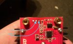
I have no idea if this will help but this 2nd picture shows how the pot is soldered in
284390_10150233945507338_629242337_7348976_4090383_n.jpg


The pot is the top three pins on the left side. You can see that two of the pins are connected together through the same path.
 
Last edited:


HIMNL9

0
Joined
May 26, 2009
Messages
5,318
Points
0
Well, first test to do is simple ..... connect a light load on the output (4Kohm or more, alsso 10K is ok, just for have a minimum load) together with a voltmeter, then power the board and set the trimmer for the maximum voltage output (quickly, or the load fry :p :D).

Then disconnect all, MAKE SURE THAT ALL THE CAPACITORS ARE DISCHARGED for not risk to blow the DMM (check with voltmeter, at least left the load connected til the capacitors are discharged), and then with the DMM on resistance scale, check the value of the trimmer when it's in the max voltage position (the 2 points marked in the pic are ok)

Based on this result, is possible to do all the rest of the work, probably just cutting a single track (the one from the trimmer that go to a SMD resistor), and just adding the potentiometer there ..... you only need first to know if at the max output voltage, the trimmer is high resistance (probably 10K or similar), or if it's at zero resistance.

BTW, what's the part number of that chip, if is readable ?
 

Attachments

  • 0001.jpg
    0001.jpg
    47.8 KB · Views: 69
Last edited:

Helios

0
Joined
Jan 7, 2011
Messages
1,341
Points
48
Ok I will let you know what I find.

Which chip are you referring to?
 

HIMNL9

0
Joined
May 26, 2009
Messages
5,318
Points
0
^ the 8 pins regulator IC, that you can see in the second pic ..... i was wondering if is a commercial product, or a custom IC.
 

Helios

0
Joined
Jan 7, 2011
Messages
1,341
Points
48
The chip says 2843A then below that Z501

Also as an update I picked this up for $25

282013_10150234631617338_629242337_7352402_7668398_n.jpg


And it has 2 4Ah lead acids in it and the bulb is labeled 12V 55W halogen so I believe they are wired in series. As I understand these should be good enough for short portable full power use right?


ALSO this big guy is finally here!
281472_10150234631952338_629242337_7352404_5973297_n.jpg
 
Last edited:

Helios

0
Joined
Jan 7, 2011
Messages
1,341
Points
48
Since this power supply only goes to 35V couldnt I just replace this pot with another pot that can be mounted externally with a knob? I dont actually need to limit it at all and I have a ammeter that I will be using to monitor the current while its running so I can just keep an eye on that.

As long as the pots have the same max resistance value it should operate the same regardless of how it was designed right? I believe this one is a 10K. So if I just desoldered this pot and soldered wires in place of the old pins and ran those wires to one of these click here and mount it to the host it should work perfect I believe. Anyone see a problem with this?

EDIT: tested the LED

261259_10150235056887338_629242337_7353391_4981015_n.jpg


This scared me a bit

261657_10150235056752338_629242337_7353390_3460231_n.jpg


But then when I turned up the voltage they all started lighting up. I think the one that was out in the first line lights up as the voltage and current increases

263676_10150235056657338_629242337_7353389_1574387_n.jpg


It flashed really bright when I first turn it on. Can that be fixed with a capacitor?

ALSO HIMNL9 The voltage increases as the pot is turned clockwise. The resistance also increases.
 
Last edited:

HIMNL9

0
Joined
May 26, 2009
Messages
5,318
Points
0
So, it's a negative feedback circuit ..... it can be an UC2843AD, it's a PWM controller regulator for offline PSU and DC/DC converters, with current sensing ..... anyway, if you don't need to limit the max voltage, the easyest way is to replace the trimmer with a 10K potentiometer, and place it accessible with an external knob, yes.

The flashing was probably due to overcurrent spikes compensation at startup, probably from the internal compensation circuitry ..... is always better to turn on these things at a lower voltage, and increase it when the driver is fully turned on, for avoid this ..... The maximum can be to find a 10K linear potentiometer with an integrated switch, and using it both for turn it on than for regulation (using a power relay drived from the switch for the positive wire, not directly the small switch on the potentiometer, ofcourse ;))
 

Helios

0
Joined
Jan 7, 2011
Messages
1,341
Points
48
Ok great that is what I will do. I do however have another issue.

At the higher power levels the LED will only stay bright for 5-10 seconds and then you can see it drop down significantly. I assume its because the batteries cannot provide the continuous current required. What do you guys think? They are 2 6V lead acid batteries wired in series. I have been trying to find the max discharge rate but I cannot seem to find it.

The batteries say only 2A initial current...that might be the problem considering I need 3A across the LED and I need more to boost the voltage...

269003_10150235762517338_629242337_7356910_6736482_n.jpg


According to my DMM I am only getting .3A to the LED! And I already thought it was bright!

It first jumped to .8A and then fell to .3 and then you can watch it fall from there about .01A per second.

Any ideas here?
 
Last edited:

HIMNL9

0
Joined
May 26, 2009
Messages
5,318
Points
0
Uhm, wait, you ARE using a good heatsink and a fan, for the LED, right ?

Anyway, it can be the batteries, you can see it easily ..... hook a DMM as voltmeter to the input (in parallel of the batteries), then look if, when it dim, the voltage of the batteries go down significantly.

Also, remember that energy don't appear magically ..... supposed you are making the LED work at 35V and around 3A, this means 105W just for the LED ..... plus the power wasted from the converter ..... supposing that working at 12V it may have 80% of efficence, it means another 18W, more or less, so it's 123W to take from a 12V battery, and this mean more than 10A from the battery ..... ;)
 

Helios

0
Joined
Jan 7, 2011
Messages
1,341
Points
48
Uhm, wait, you ARE using a good heatsink and a fan, for the LED, right ?

I have it attached to a finned heatsink and I only run it for 10 seconds or so just for testing and it doesnt even get very warm. I monitor its temperature and its just fine for short tests...although at this point its only running at 1/10th of its rated current...

Anyway, it can be the batteries, you can see it easily ..... hook a DMM as voltmeter to the input (in parallel of the batteries), then look if, when it dim, the voltage of the batteries go down significantly.

I will try that. I am 90% certain that it is the batteries. Is there anything I can do to help with this issue? Are there higher drain 6V lead acid batteries out there that I could use in place of these?

Also, remember that energy don't appear magically ..... supposed you are making the LED work at 35V and around 3A, this means 105W just for the LED ..... plus the power wasted from the converter ..... supposing that working at 12V it may have 80% of efficence, it means another 18W, more or less, so it's 123W to take from a 12V battery, and this mean more than 10A from the battery ..... ;)

I know luckily the driver is rated at 150W. I was planning to use LiFePO4 but when I saw this with built in charging I hoped it would do the job. No such luck I guess. I am debating just reassembling the spotlight and returning it.

EDIT:

I just measured the voltage at the batteries with the LED on and it instanly dropped from 13.8 to 8 and then when the LED dimmed it droped to 4V and then kept descending until I turned it off at 3V. Doesnt look good.
 
Last edited:

HIMNL9

0
Joined
May 26, 2009
Messages
5,318
Points
0
Uhm, not sure about the batteries draining ..... you can try to input more voltage in the converter, for increase efficency and decrease current draining ..... anyway, you need to check if the converter is a boost-only unit, or a buck-boost or SEPIC ..... if is a boost unit, the output voltage can never go under the input voltage, if instead is a buck-boost configuration, you can get output voltages lower than input voltages (it's easy to check, power it with 24V, and see with a DMM what is the minimum voltage you can get at the output)

Anyway, using 2 x 12V batteries, instead 2 x 6V, in serie, the input current become half.
 

Helios

0
Joined
Jan 7, 2011
Messages
1,341
Points
48
Uhm, not sure about the batteries draining ..... you can try to input more voltage in the converter, for increase efficency and decrease current draining ..... anyway, you need to check if the converter is a boost-only unit, or a buck-boost or SEPIC ..... if is a boost unit, the output voltage can never go under the input voltage, if instead is a buck-boost configuration, you can get output voltages lower than input voltages (it's easy to check, power it with 24V, and see with a DMM what is the minimum voltage you can get at the output)

Anyway, using 2 x 12V batteries, instead 2 x 6V, in serie, the input current become half.

It is a boost only driver I know that. I could wire the two 12V in parallel to get more amp discharge but I dont think two 12V batteries, even the smaller ones, will fit in here. Damn I though I could finish building this today :undecided:
 
Joined
Sep 12, 2007
Messages
9,399
Points
113
Those batteries were meant to power a 55W lamp (and probably not at the full 55W either) It isn't too surprising they can't power a 120W load. Have you tried those Li-fepo batteries?
 

Helios

0
Joined
Jan 7, 2011
Messages
1,341
Points
48
Those batteries were meant to power a 55W lamp (and probably not at the full 55W either) It isn't too surprising they can't power a 120W load. Have you tried those Li-fepo batteries?

No. I dont have any I just know they have a very high discharge. A123s can do 30C so if I was using 18650s which are rated at 1100mAh that would be up to 33A continuous. Maybe I will just pick up 5 or 6 of them and go that route.

The mailman just dropped off some packages for me. I got my reflector and my aspheric lens. The output looks really nice with the aspheric so I think im going to scrap the spotlight idea and just return it. I may just make the host out of PVC unless someone has a better idea :beer:
 
Last edited:

HIMNL9

0
Joined
May 26, 2009
Messages
5,318
Points
0
Considering the possible temperatures, aluminium is better (but finding a machinist that can work it in the shape and dimension you need, it may cost a lot :eek:)

If you made it in PVC, you will probably end needing active cooling (a fan, said in poor words), and this means no waterproof unit ..... can be a problem, if used outside, but all depend from the field of use.
 

Helios

0
Joined
Jan 7, 2011
Messages
1,341
Points
48
Considering the possible temperatures, aluminium is better (but finding a machinist that can work it in the shape and dimension you need, it may cost a lot :eek:)

If you made it in PVC, you will probably end needing active cooling (a fan, said in poor words), and this means no waterproof unit ..... can be a problem, if used outside, but all depend from the field of use.

I would love it to be aluminum but cost as you said is what is inhibiting that. I do have this coming.

CPU Athlon 64 AMD Heatsink Fan AM2 SOCKET 754 939 940 - eBay (item 110598839946 end time Aug-11-11 02:48:04 PDT)

Do you think that will be enough? I did get my AC to 3A 35V PSU today and the LED gets hot very very quickly running at a full 3A.

As far as being water proof that would be ideal but its not mandatory.


Top