- Joined
- Sep 20, 2016
- Messages
- 7
- Points
- 3
Hello! I am an occasional reader of Laser Pointer Forums. I thought I could contribute by helping with some electronics development and testing, as I am using the Benboost Mini version 5.0 for my own projects.
Due to licensing changes with EAGLE (after the acquisition by Autodesk), I've remade the Benboost Mini version 5, as created by benmwv and RHD:
http://laserpointerforums.com/f67/free-diy-open-source-boost-driver-tested-working-71433.html
I am designating all boards as Version 5.1, and I will call the original by benmwv and RHD ("LD Boost Driver lm3410 LLP3x3 v5") Version 5.0 in later parts of this post.
All Version 5.1 boards have the intent of:
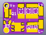
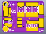
The component count remains the same, and the layout is essentially the same, except for changes for the new components.
See the attachments for Version 5-0 and 5-1 crop.jpg (this is uploaded as a .txt; download and change the extension to .jpg for viewing).
The DMP2039UFDE4 and DMP2039UFDE (Digikey: DMP2039UFDE4 and DMP2039UFDE) are interchangeable pin-wise, so different version boards and FETS can be mixed. The only differences between board versions are the names of the parts in the schematic and layout.
The DMP2039UDFE is the most cost-effective [smallest R_DS(on) for price].
Other PFETs with similar footprints are available. If one wants to swap PFETs, look for:
I have made other versions using other PFET's; as of this posting, these versions are untested except for one (which failed, likely due to my assembly method). I believe the DMP2039's are universal enough that these versions may not be needed. If requested, I can include these alternate versions in a future update. If you're curious, these FETs are in the libraries I've attached to this post.
Changes of Note:
R3 pads appear smaller than in Version 5.0; these are according to 0603 pads given by KiCAD. They appear smaller than the model shown on the most recent Digikey Template Guide Ruler, but the pad/footprint dimensions are compatible, as they soldered fine by hand.
V+ and V- pads are set for 22 AWG stranded wire maximum, or 20 AWG solid core wire.
Board dimensions are pretty much the same; OSH Park reports 11.96 mm * 9.17 mm (Version 5.1), vs 12.01 * 9.02 mm (Version 5.0).
Attached File Notes:
The KiCAD files are in the "Benboost Mini 5.1 KiCAD Files.zip" archive, but it appears that Laser Pointer Forums does not allow the upload of .zip files. Another member suggested I append the filename with .avi as a workaround. Rename the archive by removing .avi after you download.
I've only attached each board's .kicad_pcb and .sch files. Opening either will create a project in the folder, and this project will be missing libraries tied to the files. Opening the PCB should work on its own without adding libraries.
Opening the schematic will show blank devices until the instructions in "README Schematic.txt" file are followed. Schematic and footprint libraries are included in the attached ".pretty" folders.
If anything is missing or unclear, let me know!
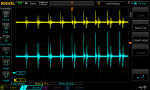
Functionality Confirmation (steady-state regulation)
For another project of mine, I am using the Benboost as a constant current LED driver for low-power flashlights. The maximum current I planned to drive is about 200 mA. I know Version 5.0 can perform at this current level, and it can also perform at my minimum setpoint of 37.5 mA. To confirm functionality, I tested the DMP2039UFDE boards with the WSON and SOT23-5 LM3410 regulators at a 37.5 mA setpoint.

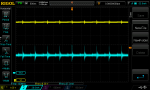
I used this as my reference for a properly functioning regulator (setpoint of 37.5 mA is shown in the RMS current, no crazy noise or waveform, 1.6 MHz frequency).

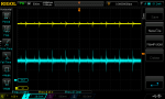
The WSON Version 5.1 appears to work just as well as Version 5.0.


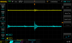
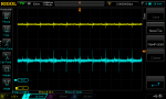
It took a couple of tries, but SOT23-5 LM3410's also work! I had tested using a board revision I had made that did not have a heatsink pad, and was therefore harder to solder.

Unfortunately, I had poorly soldered the Q1 FET on this board, and it didn't seem to be switching on. I bypassed the Q1 for this capture. Notice that there seems to be extra artifacts of some sort on the output after the switching pulse. I'm not sure what's causing this, or if this is the only other symptom bringing down the RMS current level (which should be 37.5 mA).
I've noticed I've had more trouble soldering the SOT23-5 package. If others want to solder the SOT23-5 boards by hand, make sure to test your output on a scope when you can before powering expensive diodes. Look for I_out and V_out.
I hope this is useful for others!
Note: I see that I may only be able to upload 8 files. If desired, I have zoomed-in versions of the scope captures. I will also upload 3D model images of the WSON and SOT23-5 boards.
Due to licensing changes with EAGLE (after the acquisition by Autodesk), I've remade the Benboost Mini version 5, as created by benmwv and RHD:
http://laserpointerforums.com/f67/free-diy-open-source-boost-driver-tested-working-71433.html
I am designating all boards as Version 5.1, and I will call the original by benmwv and RHD ("LD Boost Driver lm3410 LLP3x3 v5") Version 5.0 in later parts of this post.
All Version 5.1 boards have the intent of:
- Providing a fork of the Benboost regulator away from the recent licensing changes introduced by Autodesk EAGLE. These boards were made in KiCAD, which is open-source and cross-platform.
- Reducing the space required for the reverse-polarity protection PFET (Q1).
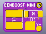
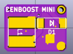
- Providing an alternative Benboost regulator using the SOT23-5 LM3410
- Continuing to be Open Source and Free to use
The component count remains the same, and the layout is essentially the same, except for changes for the new components.
See the attachments for Version 5-0 and 5-1 crop.jpg (this is uploaded as a .txt; download and change the extension to .jpg for viewing).
The DMP2039UFDE4 and DMP2039UFDE (Digikey: DMP2039UFDE4 and DMP2039UFDE) are interchangeable pin-wise, so different version boards and FETS can be mixed. The only differences between board versions are the names of the parts in the schematic and layout.
The DMP2039UDFE is the most cost-effective [smallest R_DS(on) for price].
Other PFETs with similar footprints are available. If one wants to swap PFETs, look for:
- the R_DS(on) at the voltage you plan to power your regulator with
- the current rating of the PFET (the DMP2039's are rated for at least 6 A, the Benboost Mini version 5.0's FET was rated for 8 A)
- the Drain-Source Breakdown Voltage rating of the PFET (20V or more)
- the Gate Threshold Voltage rating of the PFET (min voltage to activate the PFET, or give max R_DS(on))
I have made other versions using other PFET's; as of this posting, these versions are untested except for one (which failed, likely due to my assembly method). I believe the DMP2039's are universal enough that these versions may not be needed. If requested, I can include these alternate versions in a future update. If you're curious, these FETs are in the libraries I've attached to this post.
Changes of Note:
R3 pads appear smaller than in Version 5.0; these are according to 0603 pads given by KiCAD. They appear smaller than the model shown on the most recent Digikey Template Guide Ruler, but the pad/footprint dimensions are compatible, as they soldered fine by hand.
V+ and V- pads are set for 22 AWG stranded wire maximum, or 20 AWG solid core wire.
Board dimensions are pretty much the same; OSH Park reports 11.96 mm * 9.17 mm (Version 5.1), vs 12.01 * 9.02 mm (Version 5.0).
Attached File Notes:
The KiCAD files are in the "Benboost Mini 5.1 KiCAD Files.zip" archive, but it appears that Laser Pointer Forums does not allow the upload of .zip files. Another member suggested I append the filename with .avi as a workaround. Rename the archive by removing .avi after you download.
I've only attached each board's .kicad_pcb and .sch files. Opening either will create a project in the folder, and this project will be missing libraries tied to the files. Opening the PCB should work on its own without adding libraries.
Opening the schematic will show blank devices until the instructions in "README Schematic.txt" file are followed. Schematic and footprint libraries are included in the attached ".pretty" folders.
If anything is missing or unclear, let me know!
Functionality Confirmation (steady-state regulation)
For another project of mine, I am using the Benboost as a constant current LED driver for low-power flashlights. The maximum current I planned to drive is about 200 mA. I know Version 5.0 can perform at this current level, and it can also perform at my minimum setpoint of 37.5 mA. To confirm functionality, I tested the DMP2039UFDE boards with the WSON and SOT23-5 LM3410 regulators at a 37.5 mA setpoint.
I used this as my reference for a properly functioning regulator (setpoint of 37.5 mA is shown in the RMS current, no crazy noise or waveform, 1.6 MHz frequency).
The WSON Version 5.1 appears to work just as well as Version 5.0.
It took a couple of tries, but SOT23-5 LM3410's also work! I had tested using a board revision I had made that did not have a heatsink pad, and was therefore harder to solder.
Unfortunately, I had poorly soldered the Q1 FET on this board, and it didn't seem to be switching on. I bypassed the Q1 for this capture. Notice that there seems to be extra artifacts of some sort on the output after the switching pulse. I'm not sure what's causing this, or if this is the only other symptom bringing down the RMS current level (which should be 37.5 mA).
I've noticed I've had more trouble soldering the SOT23-5 package. If others want to solder the SOT23-5 boards by hand, make sure to test your output on a scope when you can before powering expensive diodes. Look for I_out and V_out.
I hope this is useful for others!
Note: I see that I may only be able to upload 8 files. If desired, I have zoomed-in versions of the scope captures. I will also upload 3D model images of the WSON and SOT23-5 boards.
Attachments
-
 37-5 rev5-0 WSON chckconfirm zoom out.png44.9 KB · Views: 505
 -
 37-5 rev5-1 WSON led2.png39.6 KB · Views: 510
 -
 37-5 rev51 SOT235 Re-test 1 zoom out.png47.9 KB · Views: 516
 -
 37-5 rev51 SOT235 Re-test 2a zoom out.png45.4 KB · Views: 517
 -
 37-5 rev5-1 SOT235 LED zoom out deprecated.png60.7 KB · Views: 507
 -
Benboost Mini 5.1 KiCAD Files.zip.avi46 KB · Views: 48
-
README Schematic.txt686 bytes · Views: 146
-
Version 5-0 and 5-1 crop.txt709.3 KB · Views: 121
Last edited: