- Joined
- Nov 7, 2013
- Messages
- 39
- Points
- 0
Hello,
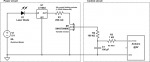
I want to create a linear current regulator for this IR diode:
http://www.eqphotonics.de/cms/cms/upload/datasheets/WSLD-808-005-3.pdf
It's a 5W diode, operating at 2.0V at about 5A.
I'd like to make use of a linear regulator, powered by a 5V, 8A switched mode power supply. (link)
The problem is that I can't use an LM317 because it's current rating is not sufficient.
I found this regulator from linear:
http://cds.linear.com/docs/en/datasheet/108345fg.pdf
It can handle up to 7.5A, and I think it works the same way the LM317 does.
The current set resistor (between OUT and ADJ) would consume about 1.25V*5A=6.25Watts of power.
I want to use a potentiometer here since I want to be able to adjust the output current.
This is where I no longer like this setup, but I don't know what other possibilities there are.
Is there any other way I can easily regulate currents up to 5A, with a linear regulator?
Kind regards
EDIT:
If we are going to use another IC for this, I'd prefer one which has an enable pin because the laser diode
must be controlled by Arduino to go on and off at regular intervals (about each 200ms)
It does not necessarily need to be an enable pin, but just any way of toggling the output.
Also, will toggling the output damage the diode in time?
Last edited:


")