Welcome to Laser Pointer Forums - discuss green laser pointers, blue laser pointers, and all types of lasers

LPF Donation via Stripe | LPF Donation - Other Methods

Links below open in new window

ArcticMyst Security by Avery

Merged 445nm Pictures and Video Thread

Joined
Sep 16, 2007
Messages
3,658
Points
113
Re: Mario's class IV 445nm Kryton + projector pics

That's what I figured... That the battery was shorting. Because cheap China P7 flashlights put 2800mA's through a cheap tail clicky...

Glad you found the problem! :)


I like to always get the negative connection to the driver input from the pill when ever possible...

But in certain builds (like Kryton's and pens), it's easier to get the negative from the diode case pin.

However, with a Micro BoostDrive, you cannot just solder the diode case pin to the negative pin like you can with a FlexDrive and connect both to the driver negative output...

You can do that with a FlexDrive because both negatives (input and output), are basically one and the same. They are continuous...

But a Micro BoostDrive is not that way.

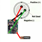
The answer, in such a build like a Kryton. Is that you can connect a wire to the diode case pin (with case neutral diodes), and then connect the wire to the input side of the Micro BoostDrive. :) But obviously you must still also connect the negative output from the driver to the negative diode pin. (and positive output to diode positive) This will work...

Ok, I see what you are doing. This makes sense now, thank you.
So what you are saying is that when using the Micro Boost, the diode cannot simply be made case negative like with the Flex, so you are using the diode's neutral case as the driver's negative input connection. That is what I figured, but I'm a "visual learner" I suppose.


jayrob

0
Joined
Sep 21, 2007
Messages
9,862
Points
113
Re: Mario's class IV 445nm Kryton + projector pics

You got it...

Not that I am doing a Kryton build. I mentioned this when just thinking about a Kryton build. Because I sold an awesome blue/black marbled Kryton to Dave a while back and was really regretting in now that we have these 445 diodes.

I'm sure you'll see an awesome picture of Dave's build in a couple of days...
 
Joined
Jun 12, 2008
Messages
1,199
Points
48
Re: Mario's class IV 445nm Kryton + projector pics

Oh and for anyone wondering, I found out that the clicky switches in my kryton were in fact due to a short - the springs were too long and would kink to the side when I pressed hard on the switch causing the spring in the switch to melt itself. I've shortened the springs and the laser works perfectly now (with the last clicky switch I had) :)


Cool good to know. :beer:

I must admit it sounded quite strange that you burnt the clickies out at only 1.5A.

However another thing that got me thinking and start pluging numbers in itself was the 1.5A figure.

Lets give the diode a "high" Vf of 5.0V@750mA = 3.75W of input power.

The microboost is ~83% efficient IIRC= ~4.5W input power

To extract 4.5W from a fresh 18650@4.2V = a current draw of 1.071A should be seen

For a discharged battery on its lasts breath @3.6V the current draw should be in the area of...1.25A

What the numbers are telling me is that unless a battery is used way down to the 3.0V level (cut-off is 3.6V IIRC), a current draw somewhat lower than 1.5A should be expected. Which combined with your news has made me a happy man. :beer: How were you measuring current btw?


One thing that has been "worrying" me is the Vf of these diodes, I have yet to receive mine and take actual measurement, as a result I have been relying on data found here and on PL. I have heard everything from 4-5V. With the flexdrive this isn't a problem, however with the microboost it does arrise. A freshly charged 18650 is 4.2V, the problem is that at lower currents the diodes Vf is probably very close to, if not lower than the figure. As the microboost is a boost only driver, this could lead to problems, when testing lower currents with a fully charged battery.


Having ordered the microboost myself, I plan on putting it through extensive testing on the o-scope. I will also examine parts and IC's doc lava is using, maybe I will get away with more than 750ma due to the lower Vf of this diode.


This sure is an exciting time for this hobby. :beer:


Dave: I thought we were already friends. :yabbem: :undecided: :na:

:beer:


Best Regards,
brtaman
 

jayrob

0
Joined
Sep 21, 2007
Messages
9,862
Points
113
Re: Mario's class IV 445nm Kryton + projector pics

I have my first 445/Micro BoostDrive build set at 475mA's and the diode is only taking 3.91 volts...

This is from a fully charged 18650. Although the Micro BoostDrive is only a 'boost circuit', it still is working fine and very stable in this configuration...

I'm sure we may find diodes of differing efficiency and forward voltage readings. And I would imagine that at higher currents, the voltage demand from the diode will be more...

Anyway, it still works very stable... :) (I'm sure the battery voltage instantly sags a little as soon as the laser comes on)
 
Last edited:
Joined
May 27, 2010
Messages
423
Points
0
Re: Mario's class IV 445nm Kryton + projector pics

Having ordered the microboost myself, I plan on putting it through extensive testing on the o-scope. I will also examine parts and IC's doc lava is using, maybe I will get away with more than 750ma due to the lower Vf of this diode.


Best Regards,
brtaman

Im running one @ 900mA
 

mfo

0
Joined
Jul 3, 2009
Messages
3,394
Points
0
Re: Mario's class IV 445nm Kryton + projector pics

No no... not to negative output!...

I like to always get the negative connection to the driver input from the pill when ever possible...

But in certain builds (like Kryton's and pens), it's easier to get the negative from the diode case pin.

However, with a Micro BoostDrive, you cannot just solder the diode case pin to the negative pin like you can with a FlexDrive and connect both to the driver negative output...

You can do that with a FlexDrive because both negatives on the driver (input and output), are basically one and the same. They are continuous...

But a Micro BoostDrive is not that way...


The answer, in such a build like a Kryton, is that you can connect a wire to the diode case pin (with case neutral diodes), and then connect the wire to the input side of the Micro BoostDrive. But obviously you must still also connect the negative output from the driver to the negative diode pin. (and positive output to diode positive) This will work... :)

Just to make sure we're on the same page, if using a microboost....

attachment.php


Correct?
 

Attachments

  • 445.png
    445.png
    153.7 KB · Views: 486
Last edited:

jayrob

0
Joined
Sep 21, 2007
Messages
9,862
Points
113
Re: Mario's class IV 445nm Kryton + projector pics

Yes that will work for a Micro BoostDrive in a situation where it is difficult to get the negative feed to the driver negative input from the pill... (such as with a Kryton build, or a pen)

As long as the module is connected to the host, the diode case will be negative. And the diode case pin can then be used to feed the driver input... (with case neutral diodes only)

Good drawing! :gj:
 
Last edited:
  • Like
Reactions: mfo

mfo

0
Joined
Jul 3, 2009
Messages
3,394
Points
0
Re: Mario's class IV 445nm Kryton + projector pics

Yes that will work for a Micro BoostDrive in a situation where it is difficult to get the negative feed to the driver negative input from the pill... (such as with a Kryton build, or a pen)

As long as the module is connected to the host, the diode case will be negative. And the diode case pin can then be used to feed the driver input... (with case neutral diodes only)

Good drawing! :gj:

Thanks, now I'm not so intimidated by the microboost drive anymore. +1.
 
Last edited:

mfo

0
Joined
Jul 3, 2009
Messages
3,394
Points
0
Re: Mario's class IV 445nm Kryton + projector pics

JellyCrab said:
Eh...sorry but...why was the not used pin...used...and connected?

Refer to the diagram + read that jayrob said.
 
Joined
Nov 5, 2007
Messages
4,919
Points
83
Re: Mario's class IV 445nm Kryton + projector pics

Its just like hooking a 12X to a Rkcstr driver and using a case negative host. If I am not mistaken you can make the diode pin go to the + or - power input for the driver. That way you can rearrange your battery configuration if you want (case positive or case negative)
 
  • Like
Reactions: mfo
Joined
Nov 5, 2007
Messages
4,919
Points
83

Trevor

0
Joined
Jul 17, 2009
Messages
4,386
Points
113
Re: Photos and Video of 445nm

The comparison shot is brilliant, thank you! Awesome job with the videos too.

I'd rep you if the system would let me.

-Trevor
 

oikos

0
Joined
Apr 16, 2010
Messages
330
Points
0
Re: Photos and Video of 445nm

yobresal! cant believe u got it built after kingdave lol i thought u would skip work just to get ur hands on these diodes a couple of hrs sooner lol... thx for the vid! u always amaze me with ur vids :thanks::thanks::thanks:

btw, i thought these were >500mw?
 
Joined
Dec 23, 2007
Messages
2,494
Points
0
Re: Photos and Video of 445nm

Wow, even with the wider beam the 445 still looks really close to the 473 in brightness. That is a very nice pic of some awesome builds!
 
Joined
Nov 5, 2007
Messages
4,919
Points
83
Re: Photos and Video of 445nm

In real life the 473nm is much brighter
@oikos thanks and yes it can go up to 500mW and past that but this driver will not go there. Not to mention there is hardly any heatsinking in this laser so it would be ill advised to go past 200mw in it.


Top