Welcome to Laser Pointer Forums - discuss green laser pointers, blue laser pointers, and all types of lasers

LPF Donation via Stripe | LPF Donation - Other Methods

Links below open in new window

ArcticMyst Security by Avery

Dave is Mean to his Diodes (445 Macros) IMAGE HEAVY

DTR

0
Joined
Jun 24, 2010
Messages
5,684
Points
113
Those pictures are really nice. Thanks for sharing.:beer:


Joined
Aug 10, 2007
Messages
526
Points
0
Amazing. The color of the facet is giving me flashbacks to the microscope scanning sequence of "The Andromeda Strain".

All it needs to do is flicker with some light and swell up with little bubbles. :D
 
Joined
Feb 1, 2008
Messages
2,894
Points
0
Can anyone else check it?

I don't know WTH I'm talking about here, but when calculating energy density, why did you use area? The length of the die ought to have some effect on the density. The cavity length/depth might be something to consider!
 

Things

0
Joined
May 1, 2007
Messages
7,517
Points
0
Dayam, Dave, thats what you get when you stick laser diodes on a lightning rod!

How much current was that poor thing pulling when it vaporised?
 

aXit

0
Joined
Sep 15, 2009
Messages
206
Points
0
Because the current only travels vertically through the die, between the two metal plates, the current density in this sense is over the constant cross-sectional area perpendicular to the current's movement.
 
Joined
Sep 20, 2008
Messages
17,622
Points
113
Thanks!

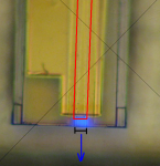
And kinda, yeah. Laser diode makers etch the ridge to form a lateral waveguide, but you don't etch all the way through the active region, so the active region is actually still in the bulk below the ridge, not "within" the ridge. The mode(s) would be located somewhere kinda like this attachment. This is not to scale and is approximate in every way, but shows the idea of hoe most of the mode is not within the ridge, but the ridge still acts to confine the mode. The mode is in red, with active region is the blue line. Without the ridge, the mode would spread out to the right and left much wider. The height of the mode is controlled by putting different layers in, and not as much by the ridge itself.

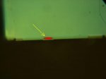
So yeah, the light is all coming out just "below" (above in my upside-down images) the ridge. Puts it into perspective, eh? The actually emitting region is still just a tiny fraction of the die; even in the last image with such huge magnification, the actual part where there is laser emission is still small.

This ridge is 15um wide, which is why it is multiple lateral modes. For single mode diodes, like everything that comes out of an optical storage drive (405nm, 660nm from Blu-Ray and DVD), that ridge is narrower, like 1 or 2 um wide. The PHR diode has a 1.5 micron ridge, for instance.

Oh, and duh, the ridge has another purpose: current guiding! The best way to do it is to inject current only straight down through the top of the ridge. So if all the current is coming in through the ridge, as much of it as possible goes into the optical mode. For stimulated emission, you need the light and the current both in the same place, so this helps to ensure that all the current ends up in the same place as the light. Which points out another cool thing about these devices: ALL the current you're putting in is passing through that ridge, which is 15 microns wide and 1200 microns long. The current comes in through the wires, flows laterally through the metal film, and then straight down through that small ridge.

I'm a bit confused...
In your mode pic... is the Laser beam coming from only the Mode (red oval area)
or the entire Blue line of your representation...:thinking:
Are the emitters along the blue line... :thinking:

28650d1281230858-dave-mean-his-diodes-445-macros-image-heavy-ridgelaser.png


Jerry
 

Attachments

  • 100x_facet_hires1.jpg
    100x_facet_hires1.jpg
    15.1 KB · Views: 208
Last edited:
Joined
Aug 25, 2007
Messages
2,007
Points
63
^Sorry for the confusion...the lasing happens in the red. The blue line is the layer (or set of layers) where all the light emission happens, but the ridge acts to hold all the laser light inside the red region. The active layers extend all the way across, but the ridge helps too hold the laser light within one little section of those layers. Does that make better sense?

On these blues, it's REALLY easy to see if you crank current up slowly from well below threshold with the laser unfocused just a little bit. You can see you outline of the die with the blue line emitting, then as you turn the current up you start getting a bright spot where the red is, than at threshold the bright spot kicks in and really takes over.


@Pullbangdead,
When constructing diodes for high power, what exactly is it that makes them more robust?

How is it that we can "kill" these diodes and still get it to lase at close to "normal" outputs? And how does it affect the emitted modes?

Up until I "killed" my 8x, I had never witnessed a "zombie" failure. Most of us have witnessed the "LED effect," and I've burned up a diode to no output, but I'm having trouble understand what has to be damaged for a diode to go "zombie."
I mean... if I look at my zombie 8X under a microscope should it look similar?

It all depends.

If you COD a diode, you no longer have that feedback that gives you lasing, but it'll function as an LED. In something like this, where the contact
layer was basically forcibly removed, it all just depends how much damage there is, and it can vary widely. I've had little tiny bits of damage make a laser stop lasing, and I've had huge amount of damage allow a laser to still work.

In this case, there's apparently a way for enough of the current to get into the diode for it to still work, and just enough things still in place for the laser to still lase. It just depends what breaks and how it break.

So to make a diode better, you have to look at what is killing it. We try to reduce voltage, to *optimize* threshold current, to improve crystal quality (which helps in many ways), improve facets and facets coatings, improve cavity design in many ways. There are dozens of ways to engineer things. You can basically test your diodes to see how they work, fix the biggest problem you think you have, and then try again to see what else is wrong.
 
Last edited:
Joined
Sep 20, 2008
Messages
17,622
Points
113
Yeah... I got it now... Thanks PBD..
Man that is a small area to emit all that power...

[EDIT]
I just found a Macro Pic of the Laser with some current
running through it... It actually shows the small area of
the die that does the lasing...:eek: These LDs are awesome...

It was posted by PL Member krazer... I think he took the
photo...

attachment.php


Jerry
 
Last edited:
Joined
Nov 17, 2009
Messages
2,031
Points
83
No photo showing up here, Jerry - I think it requires you to be logged in to PL to see it. (I think if I log in to PL and refresh here, itll work) - but that sounds like something a lot of people would like to see.

EDIT: Yup, Log in to PL, if you have an account there, and refresh this thread and it shows up fine.

That's.. damn cool looking, even if we're just looking at InGaN LED action at that point way below the threshold.
 
Joined
Aug 25, 2007
Messages
2,007
Points
63
Yep, they're pretty amazing.

Just to be as clear as I can be though, the blue light you're seeing there in that image is leakage. That's a top-down view, and the laser light is coming out of the edge, in the plane of the image. So any light that is not coming out the edge, is leakage. There's always some LED-action going on even while it's lasing, and that's what you see here: light being emitted that's not coming out as laser light. This is minimal, but you can see it in a microscope, clearly.


And to continue being clear, it's happening all along the length of the laser as well. They're using some really thick metal, so you can't see the light through the metal. With thinner metal contacts, you can see that light coming out on the whole length of the ridge. And really, the current is being put in under the metal, the whole length of the ridge, and that's where the lasing is happening. I've added some annotations to the image here. The blue arrow is the direction of the laser emission. The black scale bar show the 15 micron ridge that is visible in my other images, especially the images looking at the facet end (there are 2 sets of lines there, and the 15 micron is the outer set of lines). The red is outlining the area actually being pumped, where current is really being injected (although towards the top edge the ridge gets obscured, since depth-of-field isn't enough to get the whole thing in focus in this image). This is the area under the ridge, where current is being injected under the metal contact.

Make sense? Please tell me if anything isn't clear.
 

Attachments

  • Clarity.PNG
    Clarity.PNG
    662.2 KB · Views: 164
Last edited:
Joined
Nov 17, 2009
Messages
2,031
Points
83
Just an aside, pullbangdead - since you are 'in the industry', and I know a lot of people have dismissed it outright but i'd figure i'd ask:

*ARE* there any industrial/medical/scientific purposes for laser diodes in the yellow-orange range? Do you have an opinion on whether or not we'll ever see those? I've heard anecdotally that in LD research, they've probably already "gotten and gone past" yellow and orange wavelengths but have no marketable use for them.

I'd think there would be? 612nm hene's were produced for a long time - and now they simply are not. (I think they were used in particle counting systems?) - and I know 593 has some medical uses.

So I'm not sure - what's your opinion on these wavelengths coming out of direct diodes in the future?
 
Joined
Aug 25, 2007
Messages
2,007
Points
63
Just an aside, pullbangdead - since you are 'in the industry', and I know a lot of people have dismissed it outright but i'd figure i'd ask:

*ARE* there any industrial/medical/scientific purposes for laser diodes in the yellow-orange range? Do you have an opinion on whether or not we'll ever see those? I've heard anecdotally that in LD research, they've probably already "gotten and gone past" yellow and orange wavelengths but have no marketable use for them.

I'd think there would be? 612nm hene's were produced for a long time - and now they simply are not. (I think they were used in particle counting systems?) - and I know 593 has some medical uses.

So I'm not sure - what's your opinion on these wavelengths coming out of direct diodes in the future?

Maybe in a lab? But I doubt ever in any way that would allow us mere mortals to buy them.

And really, it may very well be possible, but the money is what is driving the research with green. It has moved FAST from violet to blue to green, thanks to the amount of money to be made. There are some research dollars out there now for going the other way too, for UV laser diodes, but not on nearly the same scale as what is being spent to get to green, and I feel like the same will be true for beyond green. There may be some universities out there working on it, token efforts, some money behind it, and some things may happen. But green has happened so fast because of the huge driving force of big-time money, and I don't see the same happening with beyond green. So I'm sure there'll be some work on it, but not on the same scale as we're seeing now.

And like everything, there are some fundamental limits. We've gotten around them so far to get to green, and who knows? Maybe we'll get around them to get farther, but with a lower driving force, it'll probably happen slower, if it progresses much at all. There are still some big things on the horizon that will change the violet/blue/green/? laser industry still to come, but how much things will change, we'll see. You never know.
 
Joined
Nov 17, 2009
Messages
2,031
Points
83
Well, thanks for that info; to say the least, I'm glad we're probably getting green. It's a shame to wonder what *hasn't* been invented because the research dollars weren't there at the time.

Hate to ask so many questions, but besides the materials, is there much of a construction difference between red and violet-blue-green LDs?

I know the ~405-510 range uses InGaN, does 650 use GaAs or AlInGaP? (or neither?)
 
D

Deleted member 16589

Guest
wow very cool i had the facet in a PHR diode crack in half before but nothing like that
very powerful microscope
what did you use to take those pictures
 
Joined
Aug 25, 2007
Messages
2,007
Points
63
Well, thanks for that info; to say the least, I'm glad we're probably getting green. It's a shame to wonder what *hasn't* been invented because the research dollars weren't there at the time.

Hate to ask so many questions, but besides the materials, is there much of a construction difference between red and violet-blue-green LDs?

I know the ~405-510 range uses InGaN, does 650 use GaAs or AlInGaP? (or neither?)

The materials themselves necessitate different designs in some ways. The basic ideas are the same, but the details are indeed different.

IIRC, which isn't guaranteed, the red diodes use AlInGap on GaAs substrates. AlInGaP can be grown lattice-matched to GaAs, making it an ideal substrate in many ways.

That's one of the problems being worked on with GaN: There's no perfect substrate like that, so a lot of work is going into making GaN substrates on which to grow GaN laser diodes.

But different crystal qualities, different optical properties, different electrical properties, all work to require some different design aspects.

wow very cool i had the facet in a PHR diode crack in half before but nothing like that
very powerful microscope
what did you use to take those pictures

Thanks. Approximations of the equipment used are pictured on the first page, several posts down.
 
Joined
Nov 7, 2008
Messages
5,725
Points
0
Just an aside, pullbangdead - since you are 'in the industry', and I know a lot of people have dismissed it outright but i'd figure i'd ask:

*ARE* there any industrial/medical/scientific purposes for laser diodes in the yellow-orange range? Do you have an opinion on whether or not we'll ever see those? I've heard anecdotally that in LD research, they've probably already "gotten and gone past" yellow and orange wavelengths but have no marketable use for them.


It may be a little stretch right now, but there are a few new display technologies that utilize a yellow source along with the usual RGB to yield even more color hue possibilities than the traditional 16.7 million colors. To me it's not inconceivable that yellow diodes could one day be used as laser TV sources to increase color range.


Top