- Joined
- Jun 22, 2011
- Messages
- 2,431
- Points
- 83
Anyone else made one?
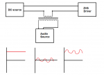
Here's mine! I used the flyback driver that Le Quack and Sigurthr helped me make. It's still a WIP:
Here's mine! I used the flyback driver that Le Quack and Sigurthr helped me make. It's still a WIP:


")