Welcome to Laser Pointer Forums - discuss green laser pointers, blue laser pointers, and all types of lasers

LPF Donation via Stripe | LPF Donation - Other Methods

Links below open in new window

ArcticMyst Security by Avery

Kryton GB round 3! MULTIPLE HOSTS!

Kenom

0
Joined
May 4, 2007
Messages
5,629
Points
63
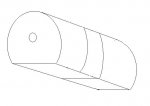
Ok I got tired of the email containing the rendering of the modified block to show up so I drew a basic thingy in paint.  I am sooo not skilled at doing this stuff.


What I can tell you about this.  It will still have the basic setup as the block with the only exception being it's round with a flat base.  Fins will still go around it for the reason specified in the next post.  Two peices that screw together with the diode pocket in it.  The flat base will be 30mm across for mounting onto a 30mm TEC if necessary.
 

Attachments

  • rounded_block.JPG
    rounded_block.JPG
    14.6 KB · Views: 85


Kenom

0
Joined
May 4, 2007
Messages
5,629
Points
63
There are two reasons that the fins will go radially around the heatsink instead of horizontally.  
1. Much easier to turn on a lathe
2. Air flow around the fins on the heatsink is unimpeded. (see illustration below)  More so when a tec is introduced and a temperature variance is created from the top to the bottom.

Not to mention it's unique looking and nobody else has done this configuration. Lava's mini module is close with a completely round unit and a small flat spot for mounting to a side bracket. This won't incorporate that though. There will be no need with it mounting flat. There will be screw holes on the bottom (2) for mounting from underneath if necessary so it doesn't move.
 

Attachments

  • illustration2.JPG
    illustration2.JPG
    42.7 KB · Views: 88

Zom-B

0
Joined
Mar 25, 2008
Messages
895
Points
28
daguin said:
[quote author=Zom-B link=1227146655/100#102 date=1228326912]70-75mm long?

The AA battery is 55mm long, the Aixiz lens threads and diode fitting are about 12mm, assuming the alu is 2mm thick, then there is only about 1-6mm left for the driver and switch?

I wouldn't mind even if it was 100mm long. One of my own design concepts fir single AA was actually 100mm long with a royal driver compartment of 19mm and a hollow front part of 9mm. You may (re-)use parts of my design if you want. I'm not doing anything with it anymore.

lathelaserdiagram2.png

Is there anything from stopping this design to be adapted to use the 10440?

Peace,
dave[/quote]
Like this?
lathelaserdiagram.png


See here for3D renderings:
http://www.laserpointerforums.com/forums/YaBB.pl?num=1223085624#15


Kenom, I'll try to do a rendering of the round block, I've been having a bit of a busy schedule the past days.


danq said:
[quote author=phoenix3200 link=1227146655/100#104 date=1228329117]I'm developing a driver that should fit flat in a 13mm space and could be driven by an alkaline/NiMH instead of a Li-Ion, and should be available by the time the Pocket Rockets come in.
I second that... though my development time is probably slower than most. I have one in progress that will be both adjustable and dimmable, and should be ready in plenty of time. I am not in a position to promise anything now, but piping up here to illustrate the point that existing driver technology need not be a constraining factor on design of these barrels.
:)
DanQ
[/quote]
I'm also designing a driver at the moment, a linear driver with low dropout, linear current control and wide configurations of current ranges. Primarily it's for fitting an aixiz (size equal to rckstr) but could also be made square. The basic concept has already been thoroughly tested, I'm just waiting on some exotic parts at the moment before I can test if the modifications (mostly miniaturization) work. Maybe we could combine forces, because our drivers will be the next gen drivers and cover a broad spectrum of input voltages. Btw, are your drivers boost or buck/boost types?

Zom-Bdriverv1board2.png
 
Joined
Oct 14, 2008
Messages
233
Points
0
Zom-B said:

Interesting design, but I'd rather mine didn't look like a flashlight (e.g. have a noticeably larger head than the body).

Zom-B said:
I'm also designing a driver at the moment, a linear driver with low dropout, linear current control and wide configurations of current ranges. Primarily it's for fitting an aixiz (size equal to rckstr) but could also be made square. The basic concept has already been thoroughly tested, I'm just waiting on some exotic parts at the moment before I can test if the modifications (mostly miniaturization) work. Maybe we could combine forces, because our drivers will be the next gen drivers and cover a broad spectrum of input voltages. Btw, are your drivers boost or buck/boost types?

Zom-Bdriverv1board2.png

Not sure if you're talking to me or danq, but...

There's not really any development left to do on mine - it's been in the "waiting for the PCB printing company got get off of their @$$" stage for over two weeks, then there's building and testing some prototypes, and then I'll order more components to offer them for sale.

Mine is based around switching regulator which should have an efficiency in excess of 80%.  It will take in anywhere from 0.9 V to 6.5 V and will output up to 5.5 V.  The finished design will be 8mm wide by 10mm long, and will be (probably) 3-4mm thick due to surface mount components on both sides of the board.
 

danq

0
Joined
Sep 18, 2007
Messages
835
Points
18
Zom-B said:
Actually, talking to both  :p
Then I'd better compose a reply ;-)
it'll take a few minutes... watch this space, I'll put it here

Zom-B said:
Btw, are your drivers boost or buck/boost types?
I didn't want to go buck/boost because of the larger part count and thus a more crowded board.  But the 405nm diodes' forward voltage falls within the voltage range of li ion rechargeables - so when the battery is at a full charge and 4.2V, that may be greater than the diode Vf, and at partial discharge it is less than Vf.

So I'm working with buck/boost.

But... running at higher currents will kick the Vf up high enough to always require a boost, so maybe there should be 2 versions, both low- and high-power; or one could just use a NiMh cell (1.2V) to keep it at boost.

Or do I have that wrong about the voltages?  :-?

DanQ
 

Zom-B

0
Joined
Mar 25, 2008
Messages
895
Points
28
One Li-Ion, or up to three NiMH (MXDL, Pocket pal) will generate a voltage lower than the V[sub]f[/sub] of PHR diodes and up (At least 5.5V, typically 5.8-6.0V) so my guess always was that a boost driver would be enough.

I don't have enough experience to design a boost driver and I also hate inductors, so I'll skip that and let other people fill that gap. I designed a linear driver for both red and violet, which works with either three NiMH or two Li-Ion respectively.
 

danq

0
Joined
Sep 18, 2007
Messages
835
Points
18
Zom-B said:
One Li-Ion, or up to three NiMH (MXDL, Pocket pal) will generate a voltage lower than the V[sub]f[/sub] of PHR diodes and up (At least 5.5V, typically 5.8-6.0V) so my guess always was that a boost driver would be enough.

I don't have enough experience to design a boost driver and I also hate inductors, so I'll skip that and let other people fill that gap. I designed a linear driver for both red and violet, which works with either three NiMH or two Li-Ion respectively.
Maybe I remembered wrong - thought the Vf on 'blues' went down to 4V.
or maybe I was thinking I need buck/boost to cover both blues and reds... my memory is bad lately, too many distractions.

I had no driver design experience either - and similarly was/am inductor-averse. Too bulky, for one thing - but just now saying that, realized that even a large inductor is smaller than a 2nd battery! I still don't like 'em though... maybe because I can't easily measure them, and their effect on a circuit isn't as intuitive as a resistor. But their magic is useful, so I'll use 'em when useful.

By the time I finish my drivers, though, there are going to be several more of you with very nice designs - so I'm not betting on becoming a driver supplier, I'll just post an idea once in a while.

:)
DanQ
 

Kenom

0
Joined
May 4, 2007
Messages
5,629
Points
63
WEll, driver options is a wonderful thing for all of these hosts. Small is good, but there's also a place for larger. The Beast is going to need to suck up to 6A off 2 18650's.
 
Joined
Oct 14, 2008
Messages
233
Points
0
danq said:
Maybe I remembered wrong - thought the Vf on 'blues' went down to 4V.
or maybe I was thinking I need buck/boost to cover both blues and reds... my memory is bad lately, too many distractions.

I tested a PHR that reached 150mA at somewhere around 5.5 V. I'm fairly certain I've seen the diode lase at 4.5 V or less as well, which means a buck/boost combination is most likely necessary if you want to support Li-Ion cells.

If you design your own, here's a few things you'll need to remember:

Battery internal resistance - you won't be able to pull 700 mA of current from a battery that was at 1.2 V disconnected and expect it to stay there. You need your driver to work at lower voltages for such a situation.

Red diodes - their negative pin is connected to the case, so you'll need to implement a high-side current monitor in your design to preserve the ground connection.

Reverse battery protection - somebody WILL hook up a battery in reverse on your design. Which would you rather damage - the battery, or the driver?

Kenom said:
WEll, driver options is a wonderful thing for all of these hosts. Small is good, but there's also a place for larger. The Beast is going to need to suck up to 6A off 2 18650's.

No thanks with my driver. You'll break my driver from all sides if you hook up two 18650's. However, at those current levels, you'll still need to find a new circuit which has minimal dropout so that you don't scorch a bunch of resistors. Probably a power MOS with a decent sized heatsink will do the trick.
 
Joined
Jul 17, 2008
Messages
601
Points
0
Your 'beast' sounds very interesting. I would love to get a high powered IR hand held, maybe 1-2 Watts would be great.

looking forward to seeing this come to life.
 

Zom-B

0
Joined
Mar 25, 2008
Messages
895
Points
28
phoenix3200 said:
Reverse battery protection - somebody WILL hook up a battery in reverse on your design. Which would you rather damage - the battery, or the driver?
I think the question should be, would you rather damage the driver or the laser diode?

A good reverse polarity protection protects both batteries and application, not just the application. Batteries could also leak if reverse polarized in another hypothetical (non-laser) application.
 

Kenom

0
Joined
May 4, 2007
Messages
5,629
Points
63
Yeah but reverse polarity protection is so easy to accomplish with a simple diode. The small amount of space that one single component takes up isn't going to be that much of an issue. Even my Groove drives were designed with reverse polarity protection.
 

Zom-B

0
Joined
Mar 25, 2008
Messages
895
Points
28
When not built right (right as in the rckstr adj driver), you're going to loose 0.7V (0.3V if shottky) of the battery power. With linear drivers this is not harmful for the efficiency, as they work on current, not voltage. For switched drivers, the efficiency will go down a lot, as they work with power conversion.


Top