

- Joined
- Sep 12, 2007
- Messages
- 9,399
- Points
- 113
I can't find the post, but someone wanted to know how one of these would work as a driver. I bought one (from a different seller than this) but it never arrived. I got a refund and bought from this guy instead. Arrived in a couple weeks or something - standard China shipping.
kE9s4Z-URLBQtm+nIlIw~~60_3.JPG)
The left pot adjusts voltage; the right pot adjusts current limit; the center pot... doesn't seem to do anything:thinking:. If anyone has an idea, lemme know. Green LED indicates power on; one red LED indicates current is being drawn; two red LEDs indicate current limit is in effect.
I used a standard 3-diodes with 1Ω shunt for the load. I varied the input voltage from 7V to 15V. They claim up to 92% efficiency, but I got anywhere from 68-75% with this load. Higher output current and lower input voltage both translate to slightly better efficiency.
If you're only interested in IF this will work as a laser driver, the answer is large pile of no; you may now close the tab.
If you're interested why it won't; read on.
Problem #1:
Current limit inexplicably stops working (jumps to >2A) if the input voltage is less than ~3.3V above load voltage.
Problem #2:
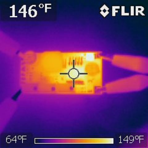
Thermal ratings are evidently designed for higher output voltage than laser diodes. It's supposed to be rated for 15W or 3A output - whichever is lower presumably. But here it is at 1A (~3W). Already getting pretty toasty:
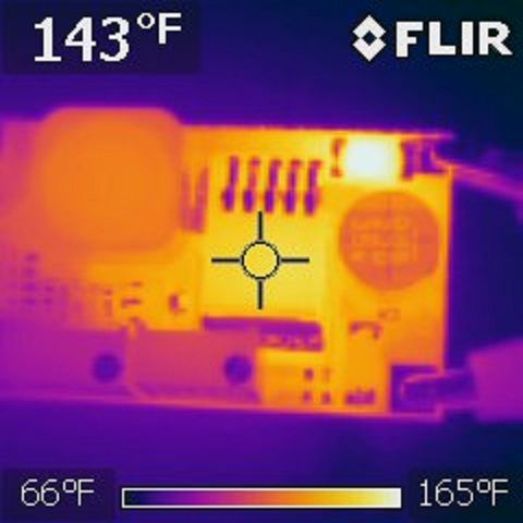
And here it is with 2.5A (10W) dumped into a resistor
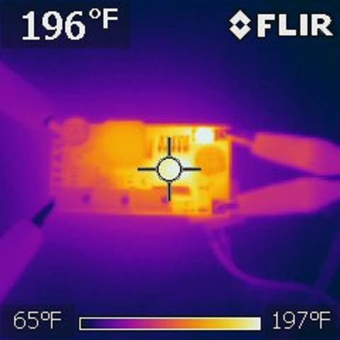
And the poor diode in the upper right is cooking away at 220F. I don't think it'll last much more than a few hours at that temperature.
Problem #3:
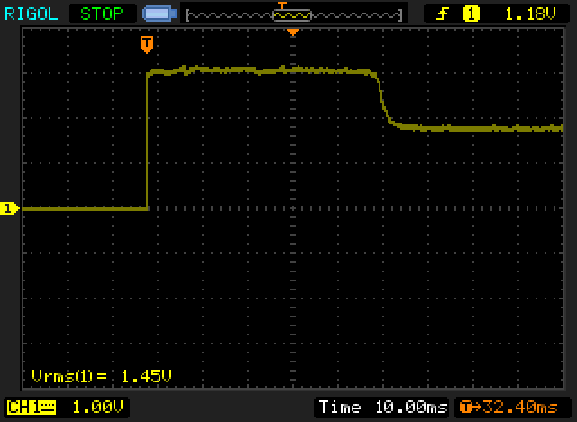
Startup spikes are downright terrifying. And it would probably be worse (to the point of blowing up my test load perhaps??) If the voltage set point was higher. As always, note the time base in each image because they change to show detail.
At 1.8A switched before the driver:
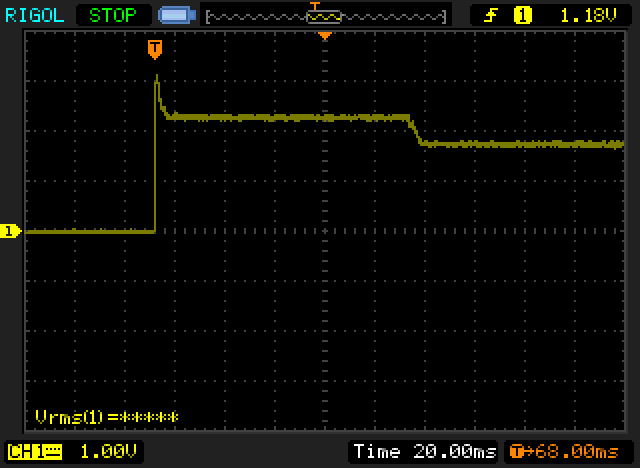
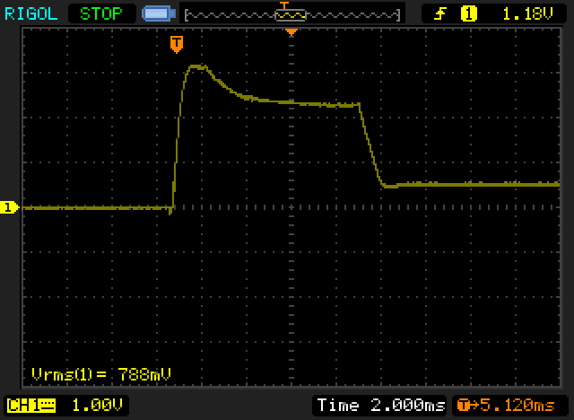
And 1.8A switched after the driver:
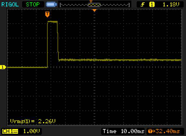
At 500mA switched before the driver:
At 500mA switched after the driver:
TL;DR: Good for battery charging, torturous death trap for laser diodes.
The left pot adjusts voltage; the right pot adjusts current limit; the center pot... doesn't seem to do anything:thinking:. If anyone has an idea, lemme know. Green LED indicates power on; one red LED indicates current is being drawn; two red LEDs indicate current limit is in effect.
I used a standard 3-diodes with 1Ω shunt for the load. I varied the input voltage from 7V to 15V. They claim up to 92% efficiency, but I got anywhere from 68-75% with this load. Higher output current and lower input voltage both translate to slightly better efficiency.
If you're only interested in IF this will work as a laser driver, the answer is large pile of no; you may now close the tab.
If you're interested why it won't; read on.
Problem #1:
Current limit inexplicably stops working (jumps to >2A) if the input voltage is less than ~3.3V above load voltage.
Problem #2:
Thermal ratings are evidently designed for higher output voltage than laser diodes. It's supposed to be rated for 15W or 3A output - whichever is lower presumably. But here it is at 1A (~3W). Already getting pretty toasty:
And here it is with 2.5A (10W) dumped into a resistor
And the poor diode in the upper right is cooking away at 220F. I don't think it'll last much more than a few hours at that temperature.
Problem #3:
Startup spikes are downright terrifying. And it would probably be worse (to the point of blowing up my test load perhaps??) If the voltage set point was higher. As always, note the time base in each image because they change to show detail.
At 1.8A switched before the driver:
And 1.8A switched after the driver:
At 500mA switched before the driver:
At 500mA switched after the driver:
TL;DR: Good for battery charging, torturous death trap for laser diodes.
Last edited:


