

Kevlar
0
- Joined
- Apr 26, 2010
- Messages
- 1,353
- Points
- 48
So I'm building a 4 motor laser Spirograph.
I'm using four 1.5V - 3.0V DC motors, four 25 Ohm Rheostat Pots, and four DPDT switches.
I originally had it all wired up without the switches but had a couple of issues.
1. It would drain the batteries really fast with 1 or more pots turned to maximum resistance.
2. When I first powered it up, and the pots set to maximum resistance the motors wouldn't turn (like I would expect). So I could lower the resistance of the pot to get the motors spinning but when I turned it back to max resistance the motor would not completely stop, just spin real slow.
So I decided instead of using SPDT where it would only give me on/off, why not use DPDT (three way, center off) switch so I could turn each motor off as well as reverse the direction.
So I wired it all up. It works great going one direction, the way its supposed to, I have control over the motors speed with the pot, but when I switch directions of the motor it goes straight to full speed and I have no control over it with the pot.
Here is a diagram I drew (sorry I'm no artist) of how I wired it.
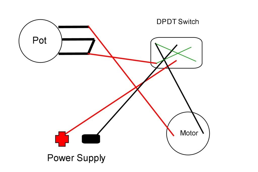
If any of this is confusing or if I've not been clear please let me know.
I'm guessing instead of wiring 2 of the leads of the pot together, I'm supposed to wire the center lead to somewhere else on the switch?
I'm using four 1.5V - 3.0V DC motors, four 25 Ohm Rheostat Pots, and four DPDT switches.
I originally had it all wired up without the switches but had a couple of issues.
1. It would drain the batteries really fast with 1 or more pots turned to maximum resistance.
2. When I first powered it up, and the pots set to maximum resistance the motors wouldn't turn (like I would expect). So I could lower the resistance of the pot to get the motors spinning but when I turned it back to max resistance the motor would not completely stop, just spin real slow.
So I decided instead of using SPDT where it would only give me on/off, why not use DPDT (three way, center off) switch so I could turn each motor off as well as reverse the direction.
So I wired it all up. It works great going one direction, the way its supposed to, I have control over the motors speed with the pot, but when I switch directions of the motor it goes straight to full speed and I have no control over it with the pot.
Here is a diagram I drew (sorry I'm no artist) of how I wired it.
If any of this is confusing or if I've not been clear please let me know.
I'm guessing instead of wiring 2 of the leads of the pot together, I'm supposed to wire the center lead to somewhere else on the switch?


