- Joined
- Dec 23, 2008
- Messages
- 3,948
- Points
- 63


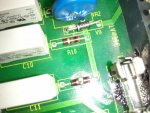
Haha, didn't occur to me that you actually meant part R10 itself when youthanks anselm... but i need to know R10
")
Bad Boys Raped Our Young Girls But Violet Gave Willingly