Welcome to Laser Pointer Forums - discuss green laser pointers, blue laser pointers, and all types of lasers

LPF Donation via Stripe | LPF Donation - Other Methods

Links below open in new window

ArcticMyst Security by Avery

Tutorial: Build Tips - 7 Color Laser Using The White Fusion Kit... from sightfx!

Joined
Oct 27, 2008
Messages
169
Points
0
Re: Build Tips - 7 Color Laser Using Adjustable Sled Mount/Heatsinks

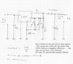
a note on using the trimmer to control the output power. The combination of a 100ohm trimmer and 10 ohm resister doesn't give you much control.
trimmer value~net resistence
10~5
30~7.5
40~8
70~8.75
90~9

the change is basically going from full to half power almost instantly (assuming 5ohm cuts output in half).


jayrob

0
Joined
Sep 21, 2007
Messages
9,862
Points
113
Re: Build Tips - 7 Color Laser Using Adjustable Sled Mount/Heatsinks

Does anybody know if there is a voltage regulator that can be used?

Something similar to a 7805 voltage regulator, which will regulate voltage to 5 volts.

Except one that will regulate to 3 volts. Or better yet, adjustable voltage!

Maybe 2.9 or so...

That way, you could use the 3.6 volt (4.2) rechargeable batteries in parallel for good capacity for the green, but adjust the voltage to the module to control the output...
Jay
 

HIMNL9

0
Joined
May 26, 2009
Messages
5,318
Points
0
Re: Build Tips - 7 Color Laser Using Adjustable Sled Mount/Heatsinks

^ I heard about a new product, it's called LM317 ..... (sorry, can't resist j/k :D)

Seriously, a lot of peoples are so used to use it as current regulator, that forgot that it's also a good voltage regulator, with a maximum current of 1,5A (but better keep it to 1A max and with a good heatsink), have an internal protection against short circuit and overload, a stability of 1% to over 70 C, and overall can regulate from a minimum of 1,2V (37 V max, but better not go over 30, and always try to keep input voltage only 3 or 4 V more than the desired output voltage, if possible, for reduce power dissipation) ..... and LM1117 is also better ;)

Or, also L200 is a good choice, it can't go under 2,85V output, but at least all the ones i used, was very stable.

Edit: datasheet of the L200, if someone need it ( i suppose all knows the 317, LOL)
http://www.datasheetcatalog.org/datasheet/stmicroelectronics/1318.pdf
 
Last edited:

jayrob

0
Joined
Sep 21, 2007
Messages
9,862
Points
113
Re: Build Tips - 7 Color Laser Using Adjustable Sled Mount/Heatsinks

Show us how!

I have plenty of LM317's, and I understand how to use them for regulating current using a resistor between the sense pins. And in that case, the diode takes what ever voltage it needs, as long as the supply voltage is available...

But if you could give an example, or ohms law on how to use it to regulate voltage, I think that it would do what I want to use it for. How about an example of how to set it up?

I have used the 7805 to regulate 5 volts output.

Can the LM317 regulate 3 volts from a 3.6 - 4.2 input supply. I would like to do something like this to power a stock O-like module with it's own driver.

Am I thinking correctly here?? It seems that if I could regulate the voltage to the module, then I could get an output power adjustment in the module...
Jay
 
Last edited:

HIMNL9

0
Joined
May 26, 2009
Messages
5,318
Points
0
Re: Build Tips - 7 Color Laser Using Adjustable Sled Mount/Heatsinks

No, the LM317 can't regulate 3 V starting from 3,6, you need a switching or LDO type for that, cause the dropout (the internal voltage drop of the regulator) is almost 3 V, so the input voltage must be at least 3 V more high than desired output voltage.

The better and cheaper one, if you can grant 4,2V, is the LM1117, that have a typical dropout of 950mV, so 3,9 / 4 V can be enough for grant you 3 V output (but also this, if the Vin fall under this limit, can't regulate in the right way, and also increasing the current, the dropout increase a little bit ..... btw, LM1117 it's 1A max, not 1,5A like 317)

The most difficult thing, about LDO regulators, is finding models that carry a decent amount of current, cause 99% of this market is made with the goal of fit them in low power devices, so almost all have very low maximum current, like, 100 mA to 250 mA ..... few exceptions.

There is a new line of very efficent LDO linear regulators, actually on the market, that have typically from 180 to 500 mV of dropout, so can do that what you want, but for them i only have the part numbers and datasheets links, cause til now i had no possibility to get some samples for make my tests ..... if you want to try to see if you can get samples (probably in any other country out Italy, it's much more easy :p), here are some datasheets with part numbers

LM1117/NCP1117 (1A)

NCP69X serie (1A)

CAT6219 (500mA)

TPS725XX family (1A, the 72501 is the adjustable one)

UCC281/381 (1A)

Or do you need schematics ?
 

jayrob

0
Joined
Sep 21, 2007
Messages
9,862
Points
113
Re: Build Tips - 7 Color Laser Using Adjustable Sled Mount/Heatsinks

What I am trying to do specifically, is to control the voltage supply to a stock O-like green module.

Now I have used a 7805 voltage regulator to regulate 5 volts supply to a FlexDrive, so it seems that it would be a good way to adjust output power of a green module by controlling the input voltage to the stock driver??

Does this thinking make sense? Since the module gives more power with a 3.6 volt battery, than it does with a 3 volt battery...

In this set up, I have two batteries that I can run in parallel, or in series. So If I need to, I can use 2 X 3.6 volt batteries in series to supply the voltage regulator.

It would be nice to have a pot, and be able to adjust for voltage output. I'm sure the module will not be using more than 400mA's or so for current...
Jay
 

HIMNL9

0
Joined
May 26, 2009
Messages
5,318
Points
0
Re: Build Tips - 7 Color Laser Using Adjustable Sled Mount/Heatsinks

Uhm, i need to see the schematic of the driver of the o-like module, for say you if it's possible or not in a safe way, but, basically, i think it can be done, also if is not the better way for do something similar .....

I mean, the driver on the o-like module is built for keep the current regulated til a certain limit, so it probably try to compensate a bit, increasing it, when you lower the voltage at the input ..... til when you reach the lower limit of regulation, then the diode just receive less current cause the voltage at the input is less than the needed for keep the regulator working correctly, and the LD just receive less current and dim .....

I think, anyway, that it can work good enough ..... basically, in the way you want to use it, the original driver just acts as "maximum current limiter", for the maximum voltage you put at the input, where instead the regulation is just done decreasing the input voltage through the voltage regulator ..... i advise you, the assembly will be not much linear, in regulation, so if you're planning to use it with a driver like in a scanner assembly, may not be the better solution ..... but for manual regulation, yes, it can work.


Edit, let me go for lunch, then i post you a schematic, if you want, cause with the 2 batteries in serie, you can use also the common 317 :)
 

jayrob

0
Joined
Sep 21, 2007
Messages
9,862
Points
113
Re: Build Tips - 7 Color Laser Using Adjustable Sled Mount/Heatsinks

After talking with Igor, I understand where the flaw in my thinking is...

All o-like modules that I have tried will give more power with a 3.6 volt rechargeable battery, than a 3 volt primary. That is where the problem is...

This made me think that I could just adjust the voltage going to the module with stock driver.

But Igor helped me to understand that if this is the case, then the driver on the cheap module is not really working properly in the first place. If it was, then it would regulate constant current with either battery, just like a FlexDrive does.

So with in mind, it's back to my original idea of replacing the module's stock driver with a DDL driver using a 1/2 watt pot like I did on my other module. (which died on me)

Anyway, everything makes more sense now. I was confused about how the modules give more power with the different voltage of the two batteries mentioned...
Jay
 

HIMNL9

0
Joined
May 26, 2009
Messages
5,318
Points
0
Re: Build Tips - 7 Color Laser Using Adjustable Sled Mount/Heatsinks

Then you can use the L200 and build custom drivers, if you want ..... they regulate both the current and the voltage, so you can preset the maximum current that you want for the diode, and set the pot for regulate the voltage to it (maybe keeping a 10 ohm 2W resistor in series to the diode, so the entire system become also less critical about the regulation) ..... this way, you can still vary the voltage, and the current preset prevent you from fry the diode for a wrong regulation or pot misfunction :)
 

jayrob

0
Joined
Sep 21, 2007
Messages
9,862
Points
113
Re: Build Tips - 7 Color Laser Using Adjustable Sled Mount/Heatsinks

Ok... thanks for your help.

According to Igor, the DDL driver should work the same way with the IR pump diode, as it does for a red. Except we know that the diode is case positive.

And this is what I have already tried, but for some reason my module did not last even at a lower output using the DDL driver.

So I scrapped that idea. But it must have just been a bad pump diode or something...
Jay
 
Last edited:
Joined
Jan 12, 2008
Messages
3,290
Points
83
Re: Build Tips - 7 Color Laser Using Adjustable Sled Mount/Heatsinks

That's strange, I've been running a green module (from dx) way above it's stock current with a DDL-driver without any problems for 5 months. :undecided:
 

jayrob

0
Joined
Sep 21, 2007
Messages
9,862
Points
113
Re: Build Tips - 7 Color Laser Using Adjustable Sled Mount/Heatsinks

Good to know! What current? Did you use a test load to set the driver?
Jay
 

jayrob

0
Joined
Sep 21, 2007
Messages
9,862
Points
113
Re: Build Tips - 7 Color Laser Using Adjustable Sled Mount/Heatsinks

Thanks for sharing!
Jay
 

HIMNL9

0
Joined
May 26, 2009
Messages
5,318
Points
0
Re: Build Tips - 7 Color Laser Using Adjustable Sled Mount/Heatsinks

Hi, sorry yesterday was in hurry, and forgot to post also the schematic :p

You can preset the maximum current with Ri, where the current is 0,45/Ri in ohm (so, as example, 450 mA for 1 ohm, 375mA for 1,2 ohm, 300 mA for 1,5 ohm, and so on), and also you increase too much the voltage, it self limit it.

The 1 Kohm pot is for the voltage regulation, and the 10Kohm trimmer in parallel is for preset the maximum voltage ..... just turn pot for the maximum resistance, then adjust the trimmer for the maximum voltage you want (can also use 4,7Kohm or 10Kohm pot, if the maximum voltage don't reach the one you want)

The 2,2 ohm resistor is just for make the regulation on the LD a little more "smooth", as you know, LD's are eager devices in fact of current, and not exactly linears ..... but can also be not used, if you want.

The diodes are for drop a bit down the output voltage, cause the L200 can't go under 2,85V, without a negative reference (and for a LD driver, building a negative reference maybe don't worth the effort ;)) ..... with the diodes, you start from approximatively 1,4V :)

And if possible, better dissipate the L200 with a heatsink :D
 

Attachments

  • L200-2.jpg
    L200-2.jpg
    234.4 KB · Views: 415


Top