Welcome to Laser Pointer Forums - discuss green laser pointers, blue laser pointers, and all types of lasers

LPF Donation via Stripe | LPF Donation - Other Methods

Links below open in new window

ArcticMyst Security by Avery

Need some help with driver

Joined
Aug 20, 2008
Messages
709
Points
0
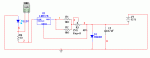
Okay, I have a little dilemma here; I want to run a case positive diode in a Kryton groove. I figured the easiest way would be to reverse the battery so that the kryton case will be positive.

The problem however is the driver; most drivers regulate the positive going into the diode and the negative simply goes to the Kryton case(negative). Would it be possible to use a normal DDL circuit or something? If not, are there any that will regulate through the negative side of the battery(a negative end regulator I believe they're called)?

Any help would be appreciated.


Joined
Oct 27, 2008
Messages
726
Points
0
I think it might work if you made the DDL driver small enough ... im not sure though.....oh that post you made was smexy... ;D ;D ... if anyone would know it would be rog :D good luck
 
Joined
Jul 24, 2007
Messages
2,749
Points
0
OK, I have come up with a plan :) Trouble is I do not own one of Kens hosts so this may not work.

The batteries go in the other way round and the drive circuit goes behind the clicky.... you will need to work out the contact to the case but the flashlight PCB.s usually have an outer ring that is press fitted to the body.
The clicky conection needs to connect between the pos battery pad and the input to the driver, I cannot believe that the easier "switch the output to the driver" would be safe.

You will need to add a capacitor discharge resister to avoid zapping the LD when you replace the batteries.......


Best I can come up with at the moment..... might work ::)

Regards rog8811
 

Attachments

  • pos_LD_laser01.jpg
    pos_LD_laser01.jpg
    38.6 KB · Views: 92
Joined
Aug 20, 2008
Messages
709
Points
0
Thanks for the input. I've considered putting the driver circuit behind the batteries but I'd like to try utilizing the space meant for the driver.
 
Joined
Sep 21, 2008
Messages
119
Points
18
Would hooking up the driver up backwards and control the current returning to the battery work??

Say you hook the negative of the diode to the positive input to the driver where the battery positive would usually go.  Hook the driver positive output (where the diode + would usually be) to the negative of the battery. Plus of battery to case, + of diode to case, in - and out - of the driver to the case.

In my head it seems like this would work at least for a simple driver like ddl...What does someone more experienced think?... I guess it could be prototyped with a test load to see..
 
Joined
Aug 20, 2008
Messages
709
Points
0
chopper said:
Would hooking up the driver up backwards and control the current returning to the battery work??

Thanks! That's what I've been trying to say all along; just didn't know how to say it... No it probably wouldn't work. The LM317 only regulates the current going into the diode...
 
Joined
Sep 21, 2008
Messages
119
Points
18
digital_blue said:
[quote author=chopper link=1227505403/0#6 date=1227740251]Would hooking up the driver up backwards and control the current returning to the battery work??

Thanks! That's what I've been trying to say all along; just didn't know how to say it... No it probably wouldn't work. The LM317 only regulates the current going into the diode...[/quote]


This is true, but by regulating the current into the diode it is regulating the current through the entire circuit... so it might,  I'm just not an expert and haven't tried it. Though this would only have a possibility of working with a linear driver that does not require the load to be in the feedback portion of the circuit.
 
Joined
Sep 21, 2008
Messages
119
Points
18
I ran simulation in Multisim and it seems to work for a DDL driver, but one or two changes must be made.

The reverse polarity protection diode (1N4001 labeled D1) must be switched in polarity from an original DDL circuit.  Also if you use a polarized electrolytic capacitor for C1 it too must be reversed to have the proper polarity.  Otherwise the simulation suggests that it would work fine.

In this circuit the LED and R4 are the dummy load with a 5v Vf on the LED.  XMM1 is a virtual voltmeter.  Remember the small side of the battery symbol is - and the big side is +.  I used 12V, 9V and 7.2V for tests.
 

Attachments

  • negative_ddl.gif
    negative_ddl.gif
    6.4 KB · Views: 93


Top