Welcome to Laser Pointer Forums - discuss green laser pointers, blue laser pointers, and all types of lasers

LPF Donation via Stripe | LPF Donation - Other Methods

Links below open in new window

ArcticMyst Security by Avery

Micro Crimp - Solder-Less Connection

Joined
Dec 28, 2009
Messages
284
Points
63
There probably are not many applications where a solder joined wire to wire connection would not be the most optimal; however for those instances where a mechanical connection would be of benefit for wire sizes AWG 24 and smaller, I believe I have found a solution. I came across a crimping tool and micro sized copper tubes designed and marketed for beading hobbyists. I immediately recognized these could be repurposed for making solder-less electrical connections in similar fashion as the common and larger crimp connectors designed for electrical industry terminations.

Note the link to the Beadalon Bead Crimp Tool - US 9.95:
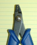
CRIMPER PLIERS for BEADS 2 - 3mm

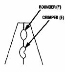
This tool features two dies: (E) to make the Initial Dimple Crimp and (F) to make the Finish Rounded Crimp. This tool measures 5” from nose to the end of comfort formed handles and 2” wide at the base of the handles.


Image of the two dies within the nose tip


I purchased two tools and used a grinder to trim down the nose edges to allow making crimps in close quarters. The second tool I ground down so just the lower dimple crimp dye remains.


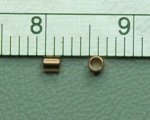
Note the link to the 2mm x 2mm Copper CRIMP Tube Beads (Qty 50 for US $4.06):
Amazon.com: (50) 2 x 2mm Copper CRIMP Tube Beads: Arts, Crafts & Sewing

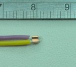
Actual measured length 1.85mm to 1.88mm, OD 1.86mm to 1.88mm, ID ~1.15mm – equivalent to #18 AWG

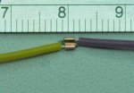
Best results are obtained when the two wires are positioned so they end up on either side of center within the Initial Dimple Crimp.

Image Side by Side wires within Initial Dimple Crimp


Image of In-Line wires within an Initial Dimple Crimp


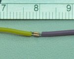
Image of the Final Rounding Crimp


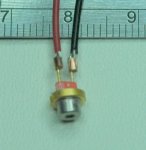
I was disappointed to find this method did not work well for diode connections, as no matter how much force was used the crimp tube would not hold fast to the smooth and rigid diode leads.
 

Attachments

  • Beadalon Bead Crimp Tool.jpg
    Beadalon Bead Crimp Tool.jpg
    6 KB · Views: 729
  • DSC_7445.JPG
    DSC_7445.JPG
    80.5 KB · Views: 833
  • DSC_7447.JPG
    DSC_7447.JPG
    50.2 KB · Views: 766
  • DSC_7449.JPG
    DSC_7449.JPG
    83.5 KB · Views: 891
  • DSC_7450.JPG
    DSC_7450.JPG
    98.1 KB · Views: 888
  • DSC_7453.JPG
    DSC_7453.JPG
    120.4 KB · Views: 915
  • DSC_7454.JPG
    DSC_7454.JPG
    123.2 KB · Views: 861
  • DSC_7440.JPG
    DSC_7440.JPG
    101.7 KB · Views: 870
Last edited:


Joined
Oct 26, 2007
Messages
5,438
Points
83
I was going to suggest using wire-wrap, but was met with the same disappointment when I tried it. The diode pins are too small for the larger sized wires the wire-wrap tool I have is meant for. The wrapped wires would just slip off.

You can try using female machine-pin headers. Those grip the pins quite well, and I have them in some of my builds (with some hot glue as back-up). Still, if time is not a problem I would just bite the bullet and solder the leads.
 

jimdt7

0
Joined
Feb 5, 2011
Messages
1,893
Points
48
I suggest you to practice soldering other things that have small leads ! Then soldering leads on a diode wont be hard ! But always remember, never leave the iron more than 3 seconds on the diode, otherwise you will frie it !
 
Joined
Jun 11, 2009
Messages
1,252
Points
63
No offense as I'm sure you spent time and money investigate this as a viable option.
But this looks like something kipkay would use in his hacks.
 
Joined
Oct 24, 2009
Messages
2,555
Points
48
Well if you wanted that why not use a conductive glue.
It can be hard to find but it works. Also not as strong as a normal solder joint.
Your best bet would be to use a female pin receptacle and put some conductive glue inside and on the diode pins.
img_female-pin-receptacle-crimp-open_250.jpg

Then slide them into place.
You will have a very firm and very permanent connection.
http://www.allelectronics.com/make-a-store/item/WG-1/CONDUCTIVE-GLUE-0.3-FL.OZ./1.html

You can also just use the glue and use heatshrink to keep things safe but i have never tested its strength.
 
Last edited:
Joined
Oct 24, 2009
Messages
2,555
Points
48
Np, But it do not know how much current the glue can take. its says low but i do not know how low.
But soldering on the diodes is no problem if you get a good soldering station with built in esd protection.
But i can understand the not wanting to risk a expensive diode.
 
Joined
May 4, 2009
Messages
5,443
Points
113
It would appear that the tube thickness is not enough to keep a tight fit on the diode lead, get thicker crimp tubes.

Worrying about a little heat from a soldering iron is a waist of time as the amount of heat that gets in there from a iron is nothing compared to the heat generated when the diode is operating, seriously !

This worry about soldering iron heat hurting laser diodes that has been floating around is baseless and I would like any one to prove me wrong.

I think it started as a sales gimmick, look my laser diodes are better than any one else's as I removed them with no heat, HA.

I remove ALL of mine with a soldering iron like they were designed to be and I have not had one failure in 100's of soldering operations.

No I think chopping at them with X-acto knives and dykes is really the wrong thing to do as it puts stress on the tiny wire leads coming out of the back of the can. this stress was never considered by the engineers that designed these laser diodes. they were however designed to be soldered :thinking:

Someone stand up and say they have burned up there diode because they got it too hot while soldering it.

I will take some temp measurements during soldering and during laser operations and we will see which is hotter if that is what needs to be done !
 
Joined
Oct 24, 2009
Messages
2,555
Points
48
i know, i have done it.
but that was back when i was using my 200w soldering gun...
Maybe it was esd but it did not work...
 

Benm

0
Joined
Aug 16, 2007
Messages
7,896
Points
113
You can try using female machine-pin headers.

I would agree with this really. The only reason i can think of you would want to make a nonsoldered connection if you need it to be easily removable. These crimped copper tubes seem somewhat problematic to remove: I'm sure they can be undone by cutting them from the side or something, but it would put a lot of strain on whatever wire was in them... in fact, unsoldering a joint would probably be easier :D
 

Benm

0
Joined
Aug 16, 2007
Messages
7,896
Points
113
i've seen them without the side part actually. I dont remember where exactly, but its available as a ready made product.

Mostly you only want to connect two pins though, and using a header is just as easy, and they are much easier to obtain.
 
Joined
Oct 24, 2009
Messages
2,555
Points
48
thor labs sells them.
But beware only 1 fits a 5.6mm diode and its not the one you want most of the time.
i got a few from thor and another place and only the one from thor worked.
But that one from o-like looks nice, a little pricey.
 
Joined
Jun 18, 2011
Messages
57
Points
8
don't u still have to solder it if u got a test socket? i thought they were designed to put solder on them instead of putting it on the diode pins. please correct me if i'm wrong.
 
Joined
Oct 24, 2009
Messages
2,555
Points
48
Yes you still solder leads to the socket.
These are usefull tho when binning diodes.
Just plug them into socket, set into test rig hold power button for 1 min and repeat.
That way you dont have to solder leads to every diode for every test.
This is not something i would use in a portable build.


Top