Welcome to Laser Pointer Forums - discuss green laser pointers, blue laser pointers, and all types of lasers

LPF Donation via Stripe | LPF Donation - Other Methods

Links below open in new window

ArcticMyst Security by Avery

Looking for general help in understanding regulator design

Joined
Jul 30, 2010
Messages
215
Points
0
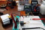
I plan on eventually making drivers for lasers, but I haven't ordered a single "laser" part yet:) (well, except those 5 Mohrengberg heatsinks, but they were cheap) What I'm doing now is making simple power supplies using a breadboard and trying them out on equally make-shift test-loads. I have a bunch of v-reg chips in my arsenal, the 2 that I have been messing with are LM7805CV and 78L05 (datasheets attached). I have encountered some problems along the way, and I feel it is because I am either not connecting the components the right way or my brain isnt connecting the results:) I am a software engineer with very very limited understanding of electronics, so I am reaching out to the EE masters on this forum who can shed some light on the topic :bowdown:

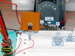
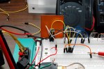
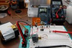
My current goal is to make a CCCV charger for LiIon. I found a power supply from a printer that puts out 16v (measured, on the box it says 10v). Step 1, I used it as the input into the LM7805 to produce 5v out, see page Fig.13 on pg.16. I get 5.05v, so far so good. I did not have a 0.33uF capacitor, so I put 3x 1uF electrolytic caps in series instead, i hope this is ok and i dont need a different type. For the 0.1uF I used a ceramic one.

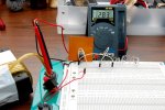
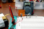
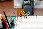
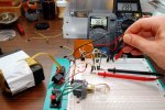
Step 2, current regulator from Fig.14. I noticed that in these diagrams they have 1/2/3 numbered pins on the chip. It looks like 1 is input voltage, 2 is output voltage and 3 is ground. But that's not how it is on the physical chip - 1 is input, 2 is ground and 3 is out! Is this a mistake in the diagrams or should I actually wire the rightmost pin on the chip directly to ground? Btw, I am assuming that you have to look at the chip from the side that has the black body with writing and the metal plate with the hole is on the back...
 

Attachments

  • L7805CV.pdf
    2 MB · Views: 351
  • LM78L05.pdf
    685.2 KB · Views: 222


Joined
Jul 17, 2010
Messages
2,160
Points
0
Can You post a picture of Your chip, and setup.

btw Capacitors in Series work like resistors in parallel, so that you not adding the 3 together. You need to run them parallel to sum them.
 
Last edited:
Joined
Jul 30, 2010
Messages
215
Points
0
Capacitors in Series work like resistors in parallel
that's what i was going for, i didnt have 0.33 so i put 3x1.0 in series instead.

here is the board with the parts laid out
attachment.php


here is 12.82V input (i said 16V before, that was wrong). I used the white wires to connect from the switch to the chip input, from the chip input to positive side of 0.33uF cap, and from the negative side of the cap to ground on the rail behind it.
attachment.php


pin #2 on the chip to ground. i dont understand why in their circuit diagram they label it 3, but im connecting the middle pin to ground in my board
attachment.php


yellow wire for the output. from chip's pin #3 to 0.1uF cap, from the cap to ground, from chip's pin #3 again to + side of the bottom set of plugs. also in there is a ground wire from the top to the bottom half of the board.
attachment.php


little multimeter measuring voltage at the bulb, big one on current duty: 4.82V and 402mA. bulb itself has resistance RL=2.6ohm, came from a car somewhere (side light or something), it's meant to run at 12V so the glow is very dim.
attachment.php


next instead of going to ground i use Fig.15 from the datasheet and add a 10ohm resistor to the output. took out yellow wire that went out and added the blue wires that go to the new resistor. moved everyone from the ground rail in the back to a common point lower. from here the orange wire is the new output.
attachment.php


new readings: 5.72V, 435mA.
attachment.php


datasheet circuit shows that the chip's nominal Vxx (should be 5V for the L7805) will be put across the resistor, as well as quiescent current will go out from pin #2 (or Id, as it's labeled in their picture). here those are measured: Vxx=3.66V, Id=2.85mA.
attachment.php
 

Attachments

  • labels.png
    labels.png
    599.7 KB · Views: 1,120
  • DSC_8864.JPG
    DSC_8864.JPG
    103 KB · Views: 807
  • DSC_8865.JPG
    DSC_8865.JPG
    102.7 KB · Views: 750
  • DSC_8867.JPG
    DSC_8867.JPG
    98.5 KB · Views: 793
  • DSC_8876.JPG
    DSC_8876.JPG
    121.9 KB · Views: 779
  • DSC_8881.JPG
    DSC_8881.JPG
    120.3 KB · Views: 587
  • DSC_8883.JPG
    DSC_8883.JPG
    121.4 KB · Views: 1,523
  • DSC_8884.JPG
    DSC_8884.JPG
    126.1 KB · Views: 755
Joined
Jul 17, 2010
Messages
2,160
Points
0
Yes You did the Capacitors correctly. I will Try to draw out what You are trying to do this evening, and get back to You. Someone else may come along and get it to you before I do. I'll post here when I sort it out.
 
Joined
Jul 30, 2010
Messages
215
Points
0
Thanx Coherent, i really appreciate your help! :beer:

i didnt really say in my last post, but i guess im trying to figure out why the measured values seem to be off from calculated. This seems to be true for Vxx, Io and Id, as none of them seem to match the datasheet. for example, there is a formula for Io in Fig.14, if i plug in the values measured i get Io=3.66/10.4+0.00285=355mA. I measured actual Io to be 435mA...
 
Last edited:

Toke

0
Joined
Jul 25, 2010
Messages
1,099
Points
0
I cannot really tell what you are trying to do, the set-up looks confusing.
As far as I can tell the LM78xx series is intended as fixed voltage regulators, with the xx being the voltage they are set for.

The 0,33uF appear in the simplest circuit in the PDF, the "Fixed Output Regulator" where the LM7805 is wired to reduce voltage to 5V.

There is a current regulator example "fig 14." in the first 2.2mb PDF, but it still looks far more complicated than using a LM317 (app. $0.6 each).

Anyway, I like the set-up with the test board and hope my local (but horribly overpriced) electronics shop is open tomorrow.

My current goal is to make a CCCV charger for LiIon.
I believe you will need one chip* to set a max Voltage of 4.2V and another one to set max current to something, maybe 100-200mA?
Or maybe use a resistor for the current limiting?

*A fixed 5V chip may not be ideal for the purpose.
 

Morgan

0
Joined
Feb 5, 2009
Messages
2,174
Points
0
^There is/was a nice little build over on CPF, (candle power forum), for a Li-ion charger from a USB port. (You might like that one too Toke!)

Have a dig about and you'll turn it up. Full tutorial too.

M
:)
 

Toke

0
Joined
Jul 25, 2010
Messages
1,099
Points
0
Looks nice Morgan.
The LTC4054 chip appears to be a specific li-ion battery charger build into a tiny surface solder chip, pretty neat. :)
 
Joined
Jul 30, 2010
Messages
215
Points
0
i've read that CPF guide using the special chip. there is also a chip like this by maxim, forgot the number. i was hoping i could use less specialized components. oh, and im sure i can get enough in samples to make more than one charger, so cost isnt really an issue.
 
Joined
Jul 17, 2010
Messages
2,160
Points
0
I can't make out what value your resistors are. Can you tell me the value for R1 & R2 if you are going by fig 15? where is the 3rd resistor connected? the formula you are using for IO is in fig 14? it's like toke said it's hard to follow, but we will make sense of this for you.
 
Joined
Jul 30, 2010
Messages
215
Points
0
i was building figure 14, sorry for the typo before when i said 15 instead. in fig 14 there is one resistor R1, mine is 10.4ohm. RL is the lamp at 2.6ohm.
 
Last edited:
Joined
Jul 17, 2010
Messages
2,160
Points
0
You forgot to add the 2.6ohm to your 10.4

Might be current limited from the supply like toke is suggesting.
 
Last edited:

Toke

0
Joined
Jul 25, 2010
Messages
1,099
Points
0
As far as I understand fig 14 the 7805 is set up like a lm317, but with 5V across the current setting resistor instead of 1.25V.

As the chip is designed specifically to maintain 5V across R1 the most likely explanations are a mis-wiring somewhere, overheating LM7805, or that your supply cannot deliver those 300-400mA.

I would strip it down to just the LM7805, R1, and lamp, in order to eliminate wiring errors.
(It is not you, if it was my circuit, my first thought would also be mis-wiring)


ETA:
On second thought, you got 5V and 10,4 Ohm that is 500mA.
You start at 12V, the bulb will take app. 1,3V that leaves 5,7V for the LM7805 to eat.

You could try with some more R1's to reduce the current, 5 of them would get you down below 100mA with less risk of overheating.
 
Last edited:

Toke

0
Joined
Jul 25, 2010
Messages
1,099
Points
0
I just noticed the part where the bulb glows a bit.

The resistance of bulbs increase quite a lot with temperature, and that is something to consider if using them for effect resistors.

The problem could be that 12V is not enough to push more than 435mA through the whole circuit when resistances are added up.
 

HIMNL9

0
Joined
May 26, 2009
Messages
5,318
Points
0
Just a pair of suggestions ;)

The 330nf capacitor at the output, and when present, the 100nF capacitor at the input, are suggested as minimum values for avoid self-oscillation of the 78xx serie in particular situations, and are not indispensable that you use exactly these values ..... if you have them in ceramic type, add them, if you just have the 1uF electrolitic ones, is enough to use one of them at input and one at output, and your circuit will work the same.

Also, remember always about the internal dropout of these regulators (that is the voltage that they "drop" naturally from the regulated one), when you design your circuits ..... that, usually, for these series of chips is around 2 to 2,5V ..... this mean that, for have the regulator that work correctly, you need to have an input voltage always a bit more high of the output voltage PLUS the dropout voltage ..... in this case, with the 7805, for have the regulator working correctly, you need to have at least 7,5 to 8V, at the input .....


Top