- Joined
- Mar 4, 2009
- Messages
- 6
- Points
- 0
I'm sure you are all well aware of the kipkay Laser Phaser project. I just recently saw the project and decided to try it on my own. My version is a little different. I received help from someone who knows a thing or two about lasers. I have little experience with lasers, but I do have some pretty good knowledge about electronics and circuits and whatnot. So I'm just gonna let you know what I plan on doing, and I would like any suggestions on how to make it better or more powerful or whatever.
I plan on getting my PHR-803T diode here: modwerx(DOT)com/shop/index(DOT)php?main_page=product_info&cPath=1_2&products_id=12&zenid=180e4b17ee46504065044fc4e8b6f8ac
My driver here: hacylon(DOT)case(DOT)edu/ebay/laser_diode/Micro_FlexDrive(DOT)php
And I'm pretty sure you don't care where I'm getting the Phaser and the RadioShack button.
So my plan is to solder the diode to the driver (I know how to do that).
Then connecting the negative wire from the driver to the negative wire coming form the battery assembly.
Connecting the positive wire from the driver to one prong of the button and the positive battery wire the the other prong. (the batter assembly I plan on using is the 2 AA battery's that the phaser already accommodates.
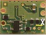
And as far as modding the driver, I will turn the pot completely clockwise which should give me about 90mW. And I also actually plan on removing 1 resistor from closest to the edge of the driver and then solder a jumper between the second resistor and the solder joint where the other resistor used to be.
Sound about right? Actually I think if I remove the resister I should readjust the pot right? If so How should I adjust it once I remove the resistor and add the jumper?
Thanks for all your help. And just as a side note this is my first project so forgive me if there I sound a bit noobish.
The pic is the resistor I will remove (X) and the jumper (yellow)
I plan on getting my PHR-803T diode here: modwerx(DOT)com/shop/index(DOT)php?main_page=product_info&cPath=1_2&products_id=12&zenid=180e4b17ee46504065044fc4e8b6f8ac
My driver here: hacylon(DOT)case(DOT)edu/ebay/laser_diode/Micro_FlexDrive(DOT)php
And I'm pretty sure you don't care where I'm getting the Phaser and the RadioShack button.
So my plan is to solder the diode to the driver (I know how to do that).
Then connecting the negative wire from the driver to the negative wire coming form the battery assembly.
Connecting the positive wire from the driver to one prong of the button and the positive battery wire the the other prong. (the batter assembly I plan on using is the 2 AA battery's that the phaser already accommodates.
And as far as modding the driver, I will turn the pot completely clockwise which should give me about 90mW. And I also actually plan on removing 1 resistor from closest to the edge of the driver and then solder a jumper between the second resistor and the solder joint where the other resistor used to be.
Sound about right? Actually I think if I remove the resister I should readjust the pot right? If so How should I adjust it once I remove the resistor and add the jumper?
Thanks for all your help. And just as a side note this is my first project so forgive me if there I sound a bit noobish.
The pic is the resistor I will remove (X) and the jumper (yellow)