- Joined
- Jul 30, 2010
- Messages
- 215
- Points
- 0
Well, I am up to 5 dead diodes now in my quest to learn how to build lasers... I appologize in advance for the long post, but I would greatly appreciate any help in troubleshooting my mistakes.
Connected LOC #1, turn on, very dim TEM02 dot. Took the head off, connected DMM in series with LD, turn on: ~50mA... LD must have died right away
Harvested LOC #2, turn the pot down to 30mA, short Vout and GND. Connect the new LD, turn on, very dim TEM02 dot. Open, using test-load set pot to 150mA, short Vout-GND, plug in LD - slightly brighter dot. Take apart, set to 300mA, short Vout-GND, plug in LD - very bright dot for 1sec, then dim, and also dead
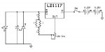
I fried my last 2 LOC diodes yesterday I am trying to build inside a flashlight host. I made a linear driver using LD1117 chip, schematic is attached below. I used 2 freshly charged Li-Ion 10440 cells, using the 3xAAA pill from the host and bridging one of the slots with a bolt+nut, the pill read 8.35V. The host's switch sits between the battery + and the driver, host is case negative.
LD and head
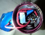
Using a 4x diode test-load I set the current to 420mA. Shorted Vout and GND, double-checked with DMM - ~1-3mV, so I figured it's safe to connect the LD. LD is pressed in Aixiz, + and - soldered to Flaminpyro's wire. Aixiz inserted in a big heatsink I bough from Matt before, heatsink inserted into flashlight head and made stable with O-rings. The heatsink and host are electrically isolated via the rubber o-rings. GND from LD soldered to the inside of the head, + wire soldered to a spring. The spring is attached to the bottom of the Aixiz/Heatsink, the idea is that it will make contact with the Vout on the host tube. This spring is isolated from the heatsink, I made a "disk" spiral from insulated wire that sits between the spring and the heatsink.
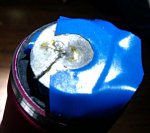
Vout
One of the pictures shows my Vout contact point for the spring: I soldered a wire to Vout from the driver, then made a round "bowl" from a catfood can and soldered the other end to that.
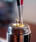
Harvesting
Cut the ribon wire, poped the LD+heatsink from the sled with a screwdriver. Using the "blob of solder" method I quickly removed the ribbon. Filed a V into the sides of the heatsink alsmost to the diode itself. Using pliers and the screwdriver I cracked the heatsink and the diode came out easily. I used a motherboard standoff and tonge-and-groove pliers to carefully press the diode into Aixiz. Soldered lead wires to +/-, this was very quick and made a nice shiny connection with both the wire and the pin envelopped in solder. I put heatshrink on it and used a blowdryer.
ESD
I have no metal pipes in my apt, so I would touch the metal frame on the table each time before touching the diode. I wore no socks and my floors are hard wood. My soldering iron has 3 prongs, but that may not necessarily mean it's grounded.
I now have no more laser diodes left to try I don't understand how I killed them or what I did wrong. The way LOC #2 died suggest to me it was capable of some lasing, but 300mA was too much current for it. This makes little sense, LOC's take 400mA+ all the time I thought... I did not have an input capacitor due to space limitations, but I'm using batteries, so I figured they wouldn't spike. Besides I have a 10uF output cap. Was it ESD during the build process that caused this?
Connected LOC #1, turn on, very dim TEM02 dot. Took the head off, connected DMM in series with LD, turn on: ~50mA... LD must have died right away
Harvested LOC #2, turn the pot down to 30mA, short Vout and GND. Connect the new LD, turn on, very dim TEM02 dot. Open, using test-load set pot to 150mA, short Vout-GND, plug in LD - slightly brighter dot. Take apart, set to 300mA, short Vout-GND, plug in LD - very bright dot for 1sec, then dim, and also dead
I fried my last 2 LOC diodes yesterday
I am trying to build inside a flashlight host. I made a linear driver using LD1117 chip, schematic is attached below. I used 2 freshly charged Li-Ion 10440 cells, using the 3xAAA pill from the host and bridging one of the slots with a bolt+nut, the pill read 8.35V. The host's switch sits between the battery + and the driver, host is case negative.LD and head
Using a 4x diode test-load I set the current to 420mA. Shorted Vout and GND, double-checked with DMM - ~1-3mV, so I figured it's safe to connect the LD. LD is pressed in Aixiz, + and - soldered to Flaminpyro's wire. Aixiz inserted in a big heatsink I bough from Matt before, heatsink inserted into flashlight head and made stable with O-rings. The heatsink and host are electrically isolated via the rubber o-rings. GND from LD soldered to the inside of the head, + wire soldered to a spring. The spring is attached to the bottom of the Aixiz/Heatsink, the idea is that it will make contact with the Vout on the host tube. This spring is isolated from the heatsink, I made a "disk" spiral from insulated wire that sits between the spring and the heatsink.
Vout
One of the pictures shows my Vout contact point for the spring: I soldered a wire to Vout from the driver, then made a round "bowl" from a catfood can and soldered the other end to that.
Harvesting
Cut the ribon wire, poped the LD+heatsink from the sled with a screwdriver. Using the "blob of solder" method I quickly removed the ribbon. Filed a V into the sides of the heatsink alsmost to the diode itself. Using pliers and the screwdriver I cracked the heatsink and the diode came out easily. I used a motherboard standoff and tonge-and-groove pliers to carefully press the diode into Aixiz. Soldered lead wires to +/-, this was very quick and made a nice shiny connection with both the wire and the pin envelopped in solder. I put heatshrink on it and used a blowdryer.
ESD
I have no metal pipes in my apt, so I would touch the metal frame on the table each time before touching the diode. I wore no socks and my floors are hard wood. My soldering iron has 3 prongs, but that may not necessarily mean it's grounded.
I now have no more laser diodes left to try
I don't understand how I killed them or what I did wrong. The way LOC #2 died suggest to me it was capable of some lasing, but 300mA was too much current for it. This makes little sense, LOC's take 400mA+ all the time I thought... I did not have an input capacitor due to space limitations, but I'm using batteries, so I figured they wouldn't spike. Besides I have a 10uF output cap. Was it ESD during the build process that caused this?