Welcome to Laser Pointer Forums - discuss green laser pointers, blue laser pointers, and all types of lasers

LPF Donation via Stripe | LPF Donation - Other Methods

Links below open in new window

ArcticMyst Security by Avery

Home made LM-317 Driver

Joined
Apr 28, 2010
Messages
174
Points
0
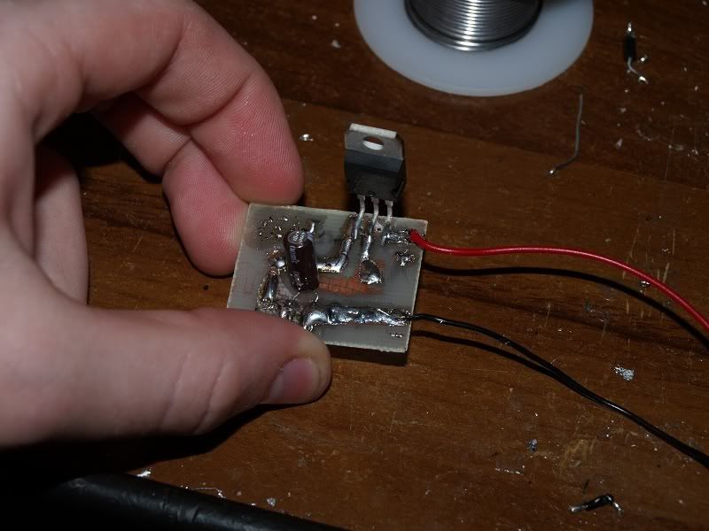
I've built this circuit based on advice I've gleaned from the forum here, and some help from HIMNL9. It's all soldered up ready to go.


Driver.jpg


I'm nervous to hook this us to my A-130 diode. I'll run through the tests I've done, please be patient with me I'm new at this.

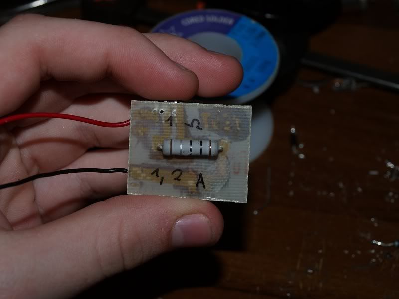
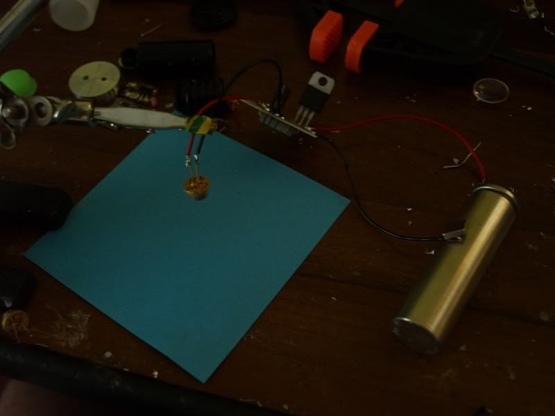
Hooked up Blu-Ray dummy load and a Red dummy load. My question is this, when I hook up my blu-ray dummy load and measure the milli-volts across the 1ohm resistor, I get a range of about 330 - 400mV. When I hook up my Red dummy load I measure 770 - 1100mV. WHY? The range is turning the 100ohm trim pot. Why the discrepancy between dummy loads, only difference between them is 2 IN4001s in series, right? Help please.
 
Last edited:


Joined
Sep 20, 2008
Messages
17,622
Points
113
A Red LD will have about a 2Volt drop across it...
A Blue or Blu-Ray LD will have about a 4Volt drop
across it... 2 different animals..

For a safe start...
I suggest you limit you driver's output with a fixed
resistor to 500-600mA with the Pot set for Max current...
Then turn the pot to minimum...
1) remove Power to the Driver
2) short the Driver's output pins to discharge the cap
3) using ESD precautions... connect your LD to the driver
4) make sure the pot is set to MIN power
5) apply power to your Driver
6) Slowly... Very Slowly increase the current to the LD
using the Pot..


Jerry
 
Joined
Apr 28, 2010
Messages
174
Points
0
Okay, I'm still hesitant to do that, which dummy load is going to be closer to these 445nm diodes in voltage drop?

I just want to say that this circuit is using components I had lying around here, but it seems to work quite well, if only I knew what current it was ACTUALLY going to feed the LD.

More reading - people are saying to use the red dummy loads, 4x IN4001 in series with a single 1W 1ohm resistor, which is what I have. Doing this I'm getting over 1000mA on max setting - 1.2A when it really heats up. By this I mean I'm measuring >1000mV across the resistor, can I extrapolate from this that my A-130 diode will be drawing 1A, and therefor outputting approx. 1W of power - according to mA / mW power graphs posted in the 445 section of the forum?
 
Last edited:

HIMNL9

0
Joined
May 26, 2009
Messages
5,318
Points
0
You need a resistor also in serie to the trimmer, for not fry it when you regulate it near the maximum current.

What type of trimmer you have ? ..... 100mW ? ..... 250mW ? ..... 1W wirewound ?
 
Joined
Apr 28, 2010
Messages
174
Points
0
It has 64W printed on it and this appears to be true. The trimmer isn't even getting warm, whereas the 0.5W 2R2 resistors in parallel are getting a bit hot.

What do you reckon HIMNL9?

DDLtrimmer.jpg
 
Last edited:
Joined
Dec 23, 2008
Messages
3,948
Points
63
it is linear driver. try hooking your dmm directly to it with out a test load. this is what i do set to the 2a setting. do not read mv....

michael
 
Joined
Apr 28, 2010
Messages
174
Points
0
Seems like noone knows what dummy load best approximates an A-130 or A-140 diode. I reckon a lot of people are building lasers and have no idea what current they are feeding their diodes.... must be.
 
Last edited:

HIMNL9

0
Joined
May 26, 2009
Messages
5,318
Points
0
LOL, sorry ..... that "64W on the body is NOT the power, is the case model ..... that looks as a normal 100mW one .....

And no, it does not become hot, when it reach the limit, the track under the cursor just fry (and being a sealed unit, you don't see nothing, opposite that on the open potentiometers, where when this happens, you see smoke) ..... if you used it only for low currents, probably it survived, but if you push it near the limit, it start to fry internally ..... you can see it just from the instability of the current, or the fact that after a certain point it does not regulate any more current ..... anyway, with these 2,2 ohm resistors in parallel, the minimum current at the output must be 1,13A .....
 
Joined
Apr 28, 2010
Messages
174
Points
0
Thanks HIMNL9 - that's about what i'm seeing when I increase the voltage to 9V. I'm going to hook it up to the diode tonight. I've checked in every conceivable way and I see no current over 1A whatever way I do it. I bought a higher value, 100uF capacitor for the input side of the circuit today so I'm ready for 1W power tonight. Wish me luck.
 
Joined
Apr 28, 2010
Messages
174
Points
0
Hooked it up tonight and it works like a dream. I don't think I'm running at quite 1W, but must be 700 or 800mA at least, so perhaps 800mW output (?)

I've got a good handle on these driver circuits now, looking forward to building the next one. Not being interested in building compact portable lasers there's no need for me to spend money on fancy micro-drivers. I'm going to build one with TTL next.
 
Joined
Oct 26, 2007
Messages
5,438
Points
83
The 445nm diode is about 4-4.2V if I recall. That means about six (6) 1N400n diodes in series (they'll each drop about 0.7V). However, if you have the series resistance (for example, to measure the current), it'll change the equation based on how much voltage the resistor is dropping. Maybe just use five (5) 1N400n diodes. Watch out though, they're only rated for about 1A.

At 700-800mA, you'll get about 600mW or so out for typical 445nm diodes. You can check the diode thread in the 445nm forum for the plots other people have.

If you're not interested in compact builds, you might consider building a larger TEC-cooled laser as well, much like Jayrob's build in the tutorials section. I think amkdeath is also working on one.
 
Joined
Sep 20, 2008
Messages
17,622
Points
113
The 445nm LDs voltage drop changes with LDs and amount of
current they are driven with...
I have one that has an fV of almost 5Volts at 1.3 amps...
So 7 Silicone rectifier Diodes should do it for over 1 Amp and
6 should do it for Under ! amp... IMO..

http://laserpointerforums.com/f65/post-your-ma-mw-51432-9.html#post724309


My Post #2 on the Blu-R voltage was meant for the 445nm as
well but jupiter must have missed it....
(besides the forward Voltage drop of the 445nm LDs is discussed
on a few Threads)

Jerry
(7200-285-25552)
 
Last edited:
Joined
Apr 28, 2010
Messages
174
Points
0
Thanks guys, my mistake. If 6 diodes equals the voltage drop roughly equivalent to the 445 then I'm probably driving mine at only 600mA max. I don't think I've come even CLOSE to 1W power output. My circuit needs a drastic redesign, there's no way it can handle more current. When I boost the input voltage to 12VDC the output doesn't rise about 4 volts but the transistor gets VERY hot and then the current drops suddenly and I disconnect rapidly. Looks like in this kind of configuration LM317 is unsuitable for currents around an amp.
 
Joined
Feb 5, 2008
Messages
6,252
Points
83

P7050094.jpg


P7050095.jpg


P7050096.jpg


P7050099.jpg


15 minutes of your time.

3 components.

1 Driver.

1.2 Amps.

Countless photons.

Priceless simplicity.

Folks, WHAT is your problem?!
Why do you need a 10 components driver when you can get the 3 component one which will outperform yours in therms of simplicity, time of contruction and ease of use?

Even if you need your current to be regulated real time (adjustable power labby), you can get a switch and use multiple resistors in paralel , you select the one you want with the switch, make 3 preset current and you have outstanding labby build.

There you go - that's my test driver for 1W 808nm diodes (and now for 445nm).

EDIT:
Thanks guys, my mistake. If 6 diodes equals the voltage drop roughly equivalent to the 445 then I'm probably driving mine at only 600mA max. I don't think I've come even CLOSE to 1W power output. My circuit needs a drastic redesign, there's no way it can handle more current. When I boost the input voltage to 12VDC the output doesn't rise about 4 volts but the transistor gets VERY hot and then the current drops suddenly and I disconnect rapidly. Looks like in this kind of configuration LM317 is unsuitable for currents around an amp.
Sorry but that's wrong.
LM317 is constant current source, it'll provide constant curren no matter what load you put on it (given the input can handle it).
You put 1 ohm of resistance on the Vref, and it'll provide 1.25 Amps though red diodes, 808nm diodes, 405nm diodes, 445nm diodes, 1n4001 diodes (no matter how many you use).

Hence, just use the damn resistor to get the driver where you want it, and hook up your diode on it. No test loads, no trimming, no smoking pots (<- uhh... what? :crackup:)
 
Last edited:
Joined
Sep 20, 2008
Messages
17,622
Points
113
Thanks guys, my mistake. If 6 diodes equals the voltage drop roughly equivalent to the 445 then I'm probably driving mine at only 600mA max. I don't think I've come even CLOSE to 1W power output. My circuit needs a drastic redesign, there's no way it can handle more current. When I boost the input voltage to 12VDC the output doesn't rise about 4 volts but the transistor gets VERY hot and then the current drops suddenly and I disconnect rapidly. Looks like in this kind of configuration LM317 is unsuitable for currents around an amp.

Your LM317 is going into thermal shutdown.... It is too Hot...

Your heat sink is too small or you are drawing much more than
1 Amp of current.

BTW... it is not a transistor.... it is a regulator... it's like calling a
boat... a car...;)


Jerry
 
Joined
Feb 5, 2008
Messages
6,252
Points
83
Your LM317 is going into thermal shutdown.... It is too Hot...

Your heat sink is too small or you are drawing much more than
1 Amp of current.

BTW... it is not a transistor.... it is a regulator... it's like calling a
boat... a car...;)


Jerry
My LM317 pictured at 1.2 A is not getting hot at let's say, 10 seconds of operation, it gets nicely warm but not hot.

OP, if your diode has 4 V drop, and driver has 2.5 V drop, then try to get the input as close to 6.5 V as possible, additional input voltage only turn into excess heat on the regulator, has no real benefits.
If you are inputting 12 V at 1A, it's 12 W of input electricap power, and let's say that your diode needs only 4W of electrical power, you have 8W of heat to dissipate on your driver, where as with 6.5 V input you'd have only 2.5 W.


Top