rhd
0
- Joined
- Dec 7, 2010
- Messages
- 8,475
- Points
- 0
I could be wrong, but doesn't that IC still require a +Vin and a -V in order to produce a +/- output?


I could be wrong, but doesn't that IC still require a +Vin and a -V in order to produce a +/- output?
")
No it doesn't....
It only requires +5VDC and ground on the input to
produce +9VDC Ground and -9VDC on the output.
Jerry
+1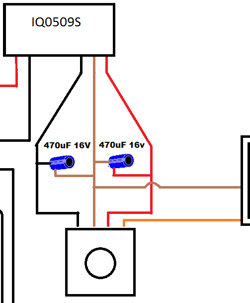
Awesome, Thanks Lasersbee and rhd.
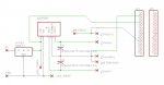
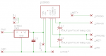
how does this look:
A few things should be noted to correct the Drawing...
A few things should be noted to correct the Drawing...
1) There should be a 1uF tantalum capacitor on the output
of the 5Volt Regulator to reduce the chance of the regulator
going into oscillation.
2) The OPHIR head connections should more correctly be
called OPH+9V and OPH-9V since the DC/DC converter
produces +/-9Volts.
Other than that it looks good to me...
Just a note: remember that tantalum capacitors are polarized. I fried an expensive $10 DC-DC converter because I put one in backwards, which shorted the power rails together when it destructed, destroying the far more expensive part. The fact that I didn't really even need the capacitor in the first place is the part that really irks me.
You're right. And I was also not crazy about my labeling of the "OPH(SIG)", but I'm not sure what else would be more fitting.
Bionic-Badger: Any reason you can think of not to simply use a ceramic non-polarized cap for the regulator?
You guys crack me up.... to replace a polarized part in case you
connect it in reverse is like saying we need a 555 with all the
pins the same and non identified so that we don't make a mistake
hooking up 8 pins...:crackup:
Just use a bit of care in connecting different types of electronic parts...
Yes... I've blown my share of incorrectly oriented parts but I've
learned to be more attentive because of it....