Welcome to Laser Pointer Forums - discuss green laser pointers, blue laser pointers, and all types of lasers

LPF Donation via Stripe | LPF Donation - Other Methods

Links below open in new window

ArcticMyst Security by Avery

Help! Does my Circuit work?

fzoid

0
Joined
Aug 27, 2010
Messages
3
Points
0
Hi,
i have bought an a A130 LD (from Casio projector, 445nm, 1W)
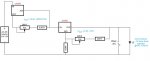
and this is my Driver for the LD. Will it work or will it burn my LD?
One LM350 is set as current regulator and one as voltage regulator,
i am an electronic newbie and i am not sure that the circuit works ^^
Sry for my English ^^
 

Attachments

  • laserdriver2.jpg
    laserdriver2.jpg
    31.3 KB · Views: 1,155
Last edited:


HIMNL9

0
Joined
May 26, 2009
Messages
5,318
Points
0
Sorry, but no ..... the first LM350, the potentiometer need to hold the same current as the load, so any "standard" pots/trimmers just smokes out and dies.

And if the first section works, you don't need the second one, cause the current regulator self-adjust the voltage for keep the current stable, so no need for a voltage regulator.

Instead use a trimmer, simply use a fixed resistor for set the current you want, in the current regulator (and add some capacitors for prevent the IC self-oscillations), and you're ok.

As example, if you want 1100mA, the resistor must be 1.25/1.1=1.136 ohm (can be used many parallel resistors for obtain the exact value), and it also must be at least 2W (better if 3 or 5) ..... a good system can be using a 3W 1,5 ohm as main resistor, and then add the others in parallel until the exact value is acquired.

Also remember that the TO220 (plastic) case version of the LM350 can hold much less power than the TO3 version (metal), and the power dissipated from the regulator is proportional to the total difference from the input and output voltage, multiplied for the current ..... so, again as example, if your diode have a Forward Voltage of, say, 3V, and you use a 12V power supply, the IC must be able to dissipate 9*1,1=9,9W ..... if the FV is 4,9V, the IC dissipate 5,4W ..... a heatsink is obligatory.
 

fzoid

0
Joined
Aug 27, 2010
Messages
3
Points
0
Sorry, but no ..... the first LM350, the potentiometer need to hold the same current as the load, so any "standard" pots/trimmers just smokes out and dies.

And if the first section works, you don't need the second one, cause the current regulator self-adjust the voltage for keep the current stable, so no need for a voltage regulator.

Instead use a trimmer, simply use a fixed resistor for set the current you want, in the current regulator (and add some capacitors for prevent the IC self-oscillations), and you're ok.

As example, if you want 1100mA, the resistor must be 1.25/1.1=1.136 ohm (can be used many parallel resistors for obtain the exact value), and it also must be at least 2W (better if 3 or 5) ..... a good system can be using a 3W 1,5 ohm as main resistor, and then add the others in parallel until the exact value is acquired.

Also remember that the TO220 (plastic) case version of the LM350 can hold much less power than the TO3 version (metal), and the power dissipated from the regulator is proportional to the total difference from the input and output voltage, multiplied for the current ..... so, again as example, if your diode have a Forward Voltage of, say, 3V, and you use a 12V power supply, the IC must be able to dissipate 9*1,1=9,9W ..... if the FV is 4,9V, the IC dissipate 5,4W ..... a heatsink is obligatory.

okay but in this circuit from daedal, the lm317 is turned in the same way, why does the pot dont die ?
and he write something about that the battery is the voltage regulator, but when i use 12v ac-dc adapter then the ld must burn out ? where is my mistake ? ^^

http://laserpointerforums.com/f42/diy-homemade-laser-diode-driver-26339.html
 
Last edited:

Toke

0
Joined
Jul 25, 2010
Messages
1,099
Points
0
HIMNL9 is correct, I will try to restate it.

It appears that the LM350, 150, and 317, are more or less identical.

They all regulate their internal resistance to keep the voltage on the adjust pin at 1,25V.
In order to use them for current regulation you have to run the whole current through a resistor that will give you a 1,25V drop at your set current.
If you include a pot in your setting circuit it must be able to take the current without burning off. There are thousands of kinds to pick from, some work some don't.
 

HIMNL9

0
Joined
May 26, 2009
Messages
5,318
Points
0
okay but in this circuit from daedal, the lm317 is turned in the same way, why does the pot dont die ?
and he write something about that the battery is the voltage regulator, but when i use 12v ac-dc adapter then the ld must burn out ? where is my mistake

Cause, basically, that schematic is wrong (or, better said, not wrong, but for sure incomplete and limited ..... it was ok, when the maximum current for a LD was 200 or 250mA, not for the high powered ones)

As you can calculate, that schematic, with these values, can give you a maximum of 300mA, approximatively, and the potentiometer, in the maximum position, must dissipate 350mW ..... potentiometers are, usually, rated at 250mW, so the low overload can also not ruin it, AT 300mA ..... but you want to use it for 1100mA, and then you have to manage with these currents and powers .....

One way for keep the circuit a bit regulable (but only a bit) is this one:

2439-lm317driver02.jpg


Here you have a RSET that take the most part of the current, and a trimmer that regulate a little bit the output ..... but, as you can see, more you go high with the output current, less you can regulate it ..... as example, if you use 1,5 ohm 3W resistor for RSET, and a 100 ohm trimmer, you can regulate only from 1210mA to 845mA (still some regulation, but not a full scale) ..... using an 1,2 ohm 3W RSET, you can regulate from 1420mA to 1050mA (higher current, but less regulation field)

An alternative can be build a current sink regulator, similarly to the flexdrive and all the others that uses the same principle, but this require a little bit more of work and components:

3355-himnl9s-crazy-generical-lab-type-current-sink-analog-modulable-laser-diode-driver-p.jpg
 
Joined
Jul 30, 2010
Messages
215
Points
0
HIMNL9, you only said to heatsink the MOSFET, but what about the OP-AMP itself? i will try this with an LM386, not sure if it's a good or bad choice of chip for this application, but i already have a bunch laying around:)
 

Toke

0
Joined
Jul 25, 2010
Messages
1,099
Points
0
The datasheet state a build in amplification of 20, adjustable up to 200 with external components. I don't think that will work as a voltage comparator. :(
 
Joined
Jul 30, 2010
Messages
215
Points
0
does the gain (20/200) relate to output current? i also have L7800 series regulators in TO-220 form, from the datasheet it says 1.5A. the LM386 datasheet doesnt mention output current, and the L7800 one doesnt mention gain...
 

Toke

0
Joined
Jul 25, 2010
Messages
1,099
Points
0
does the gain (20/200) relate to output current? i also have L7800 series regulators in TO-220 form, from the datasheet it says 1.5A. the LM386 datasheet doesnt mention output current, and the L7800 one doesnt mention gain...

Those are two very different components, and I am still trying to figure it out. :)
Voltage/current regulators are usually not described with gain, op-amp's not with output current. It does say the lm386 is rated for up to 1,25W but it is not intended as a current regulator on it's own.

I have found a handbook in basic electronics* and have some reading up to do. :)
*isbn 87-11-03814-4

It looks like gain relates only to output voltage.
 

HIMNL9

0
Joined
May 26, 2009
Messages
5,318
Points
0
HIMNL9, you only said to heatsink the MOSFET, but what about the OP-AMP itself? i will try this with an LM386, not sure if it's a good or bad choice of chip for this application, but i already have a bunch laying around:)

The op-amp does not heat at all ..... it works only as regulation element, and manage millivolts at the inputs (and have so high impedance that the power dissipated is, practically, just the one needed for drive the mosfet gate, plus its own working current)

Is the mosfet that do all the "hard work", and ofcourse, as any regulator, convert in heat all the unneeded voltage ..... so, a s "good rule", the better thing is to use power supply as low as you need .....

Let me give some examples, so it maybe appear more clear, in my poor English :p ..... suppose you have a load with a FV of 5V (mean, the minimum voltage needed from the load for work), and an op-amp that have a minimum working voltage of 6V (or +/-3V, if you prefer), then you MUST use at least 6V, for ensure the correct working environment for the op-amp ..... 6V in this case is the better one, is always better to use a power supply a little bit over the minimum, for stability ..... ofcourse, if you use an op-amp with higher minimum voltage, you are constrained to use this one, as power supply, but all the voltage over the FV of the load will become converted in heat and dissipated from the mosfet, so, still as example, if you use 6V with a 5V FV load, your mosfet need to convert in heat just the 1V over, when instead you use 12V, the mosfet need to dissipate the extra 7V in heat ..... assuming you use it at 1A, the difference is from 1W to 7W, to be continuously dissipated.

Also, i personally suggest to use high current mosfets, cause, more the mosfet is rated and manufactured for high current, more efficent is the internal structure in heat dissipation ..... also, HEXfets and TrenchMOS ones are the better ones in fact of lower internal resistance and heat transfer ..... so, also if you just need 1A, the better choice can be a 20 or 30A mosfet, or more, rated for relatively low voltages, 40 to 100V (you don't go over 12V, anyway, so no need to buy a high-cost 800V power mosfet :p)

About the op-amps, there's a lot of choice, LM358, LMH6645, MCP6001, TSV991, OPA350, TLC1078, TLC252, LMC7101, and so on, there are so much types that can be used in this schematic, that i gave intentionally no part numbers, so anyone can choose the ones that they can find more easily in their countries ..... only remember, if you use a double op-amp, instead a single one, to not left the inputs of the unused one "not connected" ..... the better way for "neutralize" an unused op-amp is to connect the output to the +IN, and the -IN to GND (not both the inputs to GND)


Top