Welcome to Laser Pointer Forums - discuss green laser pointers, blue laser pointers, and all types of lasers

LPF Donation via Stripe | LPF Donation - Other Methods

Links below open in new window

ArcticMyst Security by Avery

Building a low voltage, high power constant current laser diode driver

Joined
Sep 22, 2008
Messages
230
Points
0
Hi

I need to build a constant current laser diode driver.
I have all the logic circuit designed to monitor temperature, TEC cooling control and turn off/on the laser diode power input but I am still lacking a high power constant current driver.

In another post (http://laserpointerforums.com/f39/wtb-laser-power-supply-46196.html), I mentioned I will be using a TI PTH08T250W unit.
I will feed it 12 V from a PC power supply.
It will regulate the output to about 2.2V; which is the estmated lasing voltage for the laser diode.

However, I need to regulate the current as well to about 40-49 amps.

Does anyone has a circuit (MOSFET, etc.) to do that at about 1.5V to 2.5V?

Thanks!


HIMNL9

0
Joined
May 26, 2009
Messages
5,318
Points
0
Wait, you can OR build a constant voltage regulator, OR build a constant current regulator, not both together (cause constant current regulators keep the current stable changing the voltage, ofcourse)

You can use the same schematic that i use for make my constant current sources (attached the principle schematic), but you have to change the sense resistor and, ofcourse, parallel enough mosfets for hold the current that you need (and not knowing what mosfets you have, i cannot say you the related values, sorry)
 

Attachments

  • highcurrent reg.jpg
    highcurrent reg.jpg
    43.4 KB · Views: 8,622

HIMNL9

0
Joined
May 26, 2009
Messages
5,318
Points
0
IRFP054 is a good choice for high currents, it can easily keep 60A (64 max) continuous in ON state with a maximum voltage of 60V and can dissipate til 230W max ..... but for use it as current source in a current stabilizer, if you plan to build a variable or "modulable" system, i suggest you to use at least 2 of them, with a good heatsink (not that just one can't hold it, but i'm a maniac of safety ..... paralleling 2 of them, you divide the power dissipation that each one have to dissipate, and double the safety level of the circuit) ..... the only possible problem is that they require too much current for the gate, so you need to use a second op-amp as buffer, but this is the least problem.

Anyway, also with just one of them, coupled with a good heatsink, just for precaution, you must be safe, if you need a decent output current regulator ..... it have a decently low RDSon, so also the dissipation is relatively low ..... just optimize the input voltage of the circuit for keep the dissipated energy as low as possible, (say, 3V, max 3,5V) without compromise the function of the regulation, and you're OK (but with this current value you probably have to lower the resistance that is connected from the potentiometer and ground ..... all these values depend from the final current that you want ..... as example, i suggest you to change that part of the circuit in this way: in place of the 1 K resistor, a 4.7 Kohm trimmer, and in place of the 1 K potentiometer, a 3.3Kohm one, and considering that this circuit was designed for lower mosfets, change the 47K resistor between the positive and the gate with a 10Kohm one .....

Depending from your setup, may also be necessary to use a 0.05 ohm or less resistor as sense resistor, instead 0.1 ohm ..... with these low values, is usually better to use constantane wire resistors, or constantane plate ones, and can be put more than one in parallel, if you don't find the needed values ..... it's practically impossible to measure them with normal multimeters, you need a milliohmeter, or just buy them already made for the needed values ..... also, considerate that also this resistor hold the same current that you have at the output, so you need to dimension it for the right power ..... just as example, if you use a 0.01 ohm one, with 50 A you have 0.5V on it, that means 25W of dissipation ..... so, at least 40 or 50W resistor is needed for not "cook" it .....

Then, you can set a maximum current that is under the limit of the mosfet, during the setup ..... turning both the trimmer and the potentiometer for the minimum current, with an amperometer in serie to the load, powering up the unit, turning the potentiometer for the maximum current (keeping an eye on the amperometer :p
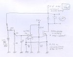
), then turning the trimmer until you reach the maximum value that you want, paying attention to never go over 55A or similar ..... in this way, the current remain regulable in a certain range, but never go over the limit set with the trimmer.

Ofcourse, i suggest you to do these tests using a dummy load that can hold these currents and dissipate these powers ..... the better choice can be a LEDed diode bar similar to the good one, still working as diode and eating power, but already damaged as laser, so it's the more similar to the real one ..... in alternative, a low value BIG resistor, like, 0.1 ohm 200W wire resistor, can be ok

BTW, if you find a precision 0.01 ohm resistor, you can easily use it also for measure the current, just placing a millivoltmeter in parallel with the resistor ..... at 200mv scale, the usual scale of these meters, each mV is 1A, and cause they are 3 1/2 cyphers, you have an instrument that measure til 199A with 100mA steps

And, just as suggestion, if you don't find the right type of shunt resistor in any electronic shops (is not easy, i know it for personal experience), there's an alternative on ebay, that is a bit uncommon, but that can work good ..... there's for sale a lot of relatively cheap lcd or led meters, that are proposed already set for certain ranges, like, 200VAC, 20VDC, 200ADC , and so on ..... the 200A DC ones, are sold with a shunt resistor that is already the right value and power that you probably need ..... ;)
 

HIMNL9

0
Joined
May 26, 2009
Messages
5,318
Points
0
Uh ..... why my posts are gone before your one ? ..... i posted after you ..... your post hour shifted from AM to PM ..... maybe Avery is upgrading something in the forum DB .....

EDIT: heard about this from c0ld, and he said that it's due to a MB change and clock problems ..... it's normal, and will cause some troubles with post orders for the next few hours (probably 3 or 4, if the time that i see is right.

Posted this as advice, as c0ld asked, for the others that may have or notice the same thing.
 
Last edited:
Joined
Sep 22, 2008
Messages
230
Points
0
Thanks, HIMNL9.

I have no idea what MOSFET to get. With your experience, would you recommend something to do 40 to 49 amps?
 
Joined
Feb 21, 2008
Messages
1,056
Points
0
Also with MOSFETs, you must be concerned with the Vgs, or voltage required to turn on the gate. Some MOSFETs need 20V to be fully "on". A logic level MOSFET will have a more reasonable gate voltage requirement. There are logic level MOSFETs that can handle a lot of current, and 5V to the gate will have it fully turned on.

EDIT : Nearly forget ... you also need the lowest possible Rds ON value for your MOSFET.
 
Last edited:
Joined
Sep 22, 2008
Messages
230
Points
0
Thanks for all that information!!

I think I have a problem..
I an using a TI PTH08T250W to regulate the voltage from a PC power supply 12V to around 2.2V output...

With 2.2V, I can't even turn on the MOSFET whether logic level or not....
this is getting tough... HELP!!
 
Joined
Jan 7, 2007
Messages
6,309
Points
83
I believe there is a circuit which feeds the sence input of the PTH08 module to make it CC. It may be on the data sheet for the device. It uses an external OP amp and a sence resistor. It can be done.
I plan to run mine with manual voltage control metering V & A. I don't need full power yet. I'm just trying to get the beam under control.

HMike.
 
Joined
Sep 22, 2008
Messages
230
Points
0
Hi Mike

I read thru the data sheet. There is no mention about Current Control using an external OP amp....

There are stuffs like external resistor to fix output voltage, calculation of input and output capacitors, TurboTrans feature, inhibit pin, low voltage lock .... etc .... but no mention of current except that if there is a over current, the unit will shut down and attempt to resume function....

Where can I find this CC information? Thanks!
 

HIMNL9

0
Joined
May 26, 2009
Messages
5,318
Points
0
^ scroll up, i posted yesterday, but cause the server clock problem, the posts gone before your one (just in case you have not see it :whistle:)
 
Joined
Sep 22, 2008
Messages
230
Points
0
Hi Mike

I think the sense pin you mentioned is the voltage sense; there are 2 sense + and sense -.

There is no current control for this module; looks like I just blew another $79 :(
 
Joined
Jan 16, 2013
Messages
1
Points
0
^ scroll up, i posted yesterday, but cause the server clock problem, the posts gone before your one (just in case you have not see it :whistle:)

Hi HIMNL9, I am Thuong, i come from Vietnam. Now i have a project about constant current use to hight power laser diode. But i can not understand how to designe the circuit constand current. Can you help me about it?


Top