Sigurthr
0
- Joined
- Dec 11, 2011
- Messages
- 4,364
- Points
- 83
I've toyed with the idea of contacting a machinist for simple stuff but never looked into pricing. Nice to hear it's that cheap!


I have learned a few things by watching this thread that i have wanted to learn! I have a couple questions and a couple things i would like to point out if I may!
1st question. RHD if I understand the build the coding is for the start up sequence of the rgb and it starts each color in series as to not over tax the power source and the drive. By having the momentary gap in the sequence say it lights the red and couple seconds later green and last the blue if my understanding is correct!
2nd question. what are each of the diodes going to be producing as of power is it mw or watts?
3rd and last question! Because of the nature of different wavelengths and the power requirements of them how are you going to get the required voltage from one or two lithium ions?
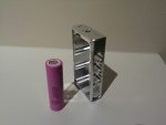
My thoughts! If your going to portable and more than 2watts at that size then you must be using a boost driver! I am still learning about drivers and stuff but here is the thing to get that kind of power I am assuming that you will be using some high drain 18650 or some thing similar over 3000 mah now with two you will get 7.4 volts and I know that 445 need just that to run over 1 watt! so is this going to be two parts? I mean are you going to have the actual laser assembly in one part and a separate battery box connected by a usb cable or some thing similar? I would think that if you used a currently available portable power banks such like the ones on FastTech you could reduce the over all size of the laser assembly. Mini In the Box has 20,000 mah solar recharging units for 40 dollars. by connecting the laser to that power bank you would get either one amp or rwo point one amps and add that to a boost you could theoretically get 3 to 4 amps of power!
The second thing is by taking the power directly out of the main laser you can save space for switches and the like.
Sorry if my thoughts dont have merit! I still learning and if I could do some thing like this that is the way I would go thanks for your time
")
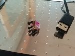
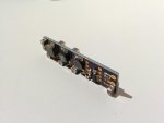
Received parts for my Micro Dichros today.
Surely the world's smallest adjustable dichro mounts.

EDIT: I think this will end up becoming a build thread.
Impressive! Are those screws M2?
How do I actually get code on this chip now? I assume it's not as simple as plugging the USB programmer in and getting a drive letter to copy the code to?
ATTiny85 Procedure
Load Arduino IDE.
Programmer: AVR ISP
Board: Arduino UNO
Example: ArduinoISP
Plug in UNO, no ATTiny85 ISP Shield
Upload Sketch.
Reset UNO.
Attach ATTiny85 ISP Shield.
Programmer: Arduino as ISP
***Board: ATTiny85 1MHz***
Load Sketch.
Upload Sketch.
Reset UNO.
***8MHz Operation;
Board: ATTiny85 8MHz
Burn Bootloader.
Load Sketch.
Upload Sketch.
Reset UNO.