Welcome to Laser Pointer Forums - discuss green laser pointers, blue laser pointers, and all types of lasers

LPF Donation via Stripe | LPF Donation - Other Methods

Links below open in new window

ArcticMyst Security by Avery

Advice on mounting a T0-3 Diode in a host!

Fiddy

0
Joined
May 22, 2011
Messages
2,726
Points
63
G'day,

So lately Ive been wavelength hunting, and when i stumbled upon a Class 4 670-690 diode i got excited.

Its a 500mW 670-690nm T0-3 diode on eBay, i plan to put it into a host, a fairly large one.

t0-3laserdiode.jpg


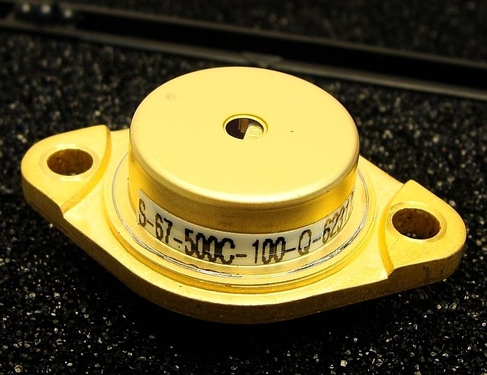
Spec sheet: COHERENT S-67-500C-100-Q

The unit has a TEC and thermistor but i dont intend on running them at this stage.

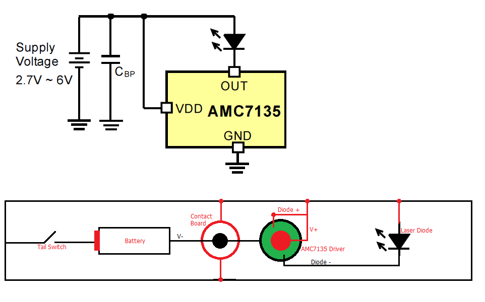
The diode is also case positive, so ive done some testing with drivers and i can use a 16 mode AMC-7135 boards i love, ill use 3x AMC chips to regulate 1050mA which is what the spec sheet says it can handle.

Im going to run the battery case positive, but a problem arises there, the AMC-7135 driver contact patch is a Positive patch, to get around this, im going to have a blank contact board, with a black wire coming off the the center positive contact patch, going to the negative on the AMC driver! Doesn't make sense? here's a diagram of what i intend.

CasepositiveLaserdriver.png


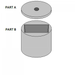
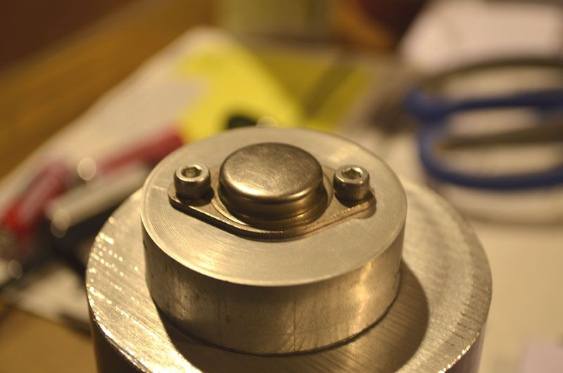
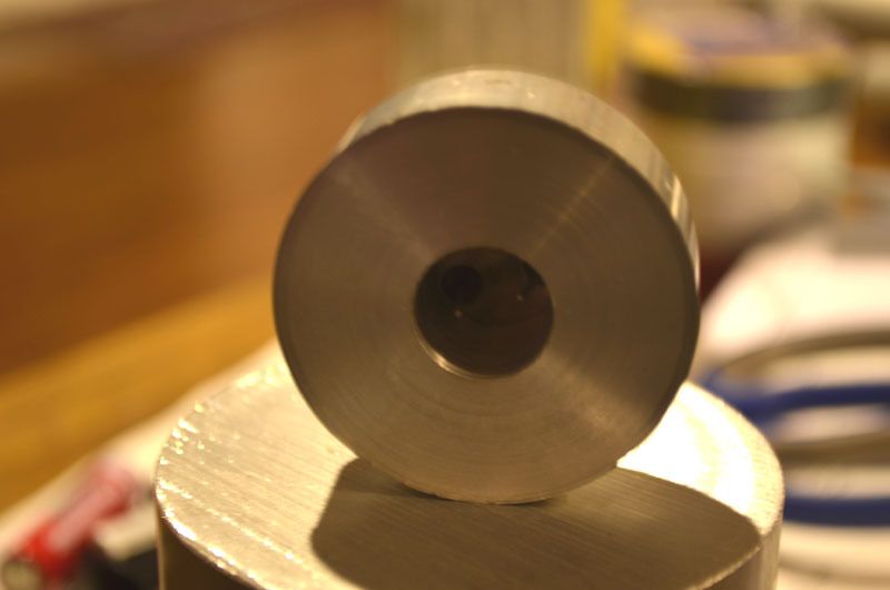
Now for the mounting of the diode, i plan to make my own mount out of aluminum based on the dimensions on the spec sheet, Now my paint drawings art great but here's a diagram of what i plan on:

t0-3laserdimensions.jpg


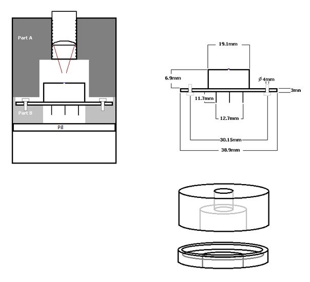
Does that seem like a good way to mount this? do you have a better idea that i can make? im open to suggestions.

Also could you recommend a decent host that fits the following criteria:

  1. voltage must be 4.2V max in, so single cell or multli parallel batteries.
  2. At least 50mm in head diameter, at least 40-45mm reflector size (diode is 39mm wide).
  3. Cant be a saik, TK-35 or a RL-2088 as i have one of them already :)

Any help,tips would be appreciated!

Cheers!

Fidz.
 
Last edited:


Hiemal

0
Joined
Dec 27, 2011
Messages
1,443
Points
63
Question; why would you use a linear driver?

If you use a buck driver a few of your host problems would be solved; that and you'll get longer run times as well.

If you're positive you want to stay with a linear driver, wouldn't a Maglite with a cell spacer work?
 

Fiddy

0
Joined
May 22, 2011
Messages
2,726
Points
63
i like my modes :) simple driver too, not really worries about run times on this one, was thinking that but there a bit to big for my liking as a laser.
 

benmwv

0
Joined
Sep 10, 2010
Messages
1,380
Points
48
It would be pretty hard to use a buck driver (which are either continuous ground or both sides isolated) on a case positive diode. AMC7135 is a perfect fit for this diode I think.

Fiddy I think if a diode has a built in TEC it might harm the diode to run it without the TEC on. If its not turned on it wouldn't transfer heat from the diode to the can very good right? I would use an amc driver for the diode and another for the TEC. Bridge the TEC+ to the case pin and then use maybe 6x AMC for it (2.1A)?

It would be great if there was some way to make that heatsink from one piece because most of the material is in the top, not directly connected to the diode. I had an idea to move most of the material from part a to part b:
attachment.php

Down inside just out of view would be a flat area with a hole in the middle for the pins. Diode would get screwed down there and then the top plate could be glued on or held by the Hosts retaining ring. Can you make something like this?
 

Attachments

  • TO-3 HS.png
    TO-3 HS.png
    7.1 KB · Views: 702

Fiddy

0
Joined
May 22, 2011
Messages
2,726
Points
63
I was thinking the same with the tec, im not sure of the current it will handle tho, where did your 2.1A come from?

the TEC's pins are isolated too.

Interesting design, i dont see how the diode sits in the square hole tho?

i cant do square stuff as im only on a lathe not a CNC or mill.
 

benmwv

0
Joined
Sep 10, 2010
Messages
1,380
Points
48
Random guess :whistle: I figured it would probably need to handle about double the current to cool it effectively.

The square hole would stop about an inch down then the would be a smaller circle hole in the middle for the pins to go out. The diode would just screw into the flat part at the bottom of the square hole.

If you can find a big enough host you could make a 40mm circle hole instead of the square but that would cut out a lot of the heatsink mass.
 

Fiddy

0
Joined
May 22, 2011
Messages
2,726
Points
63
Small update,

i found a T0-3 transistor that is the really close in all dimensions to the diode im going to use, so i made a test heatsink for it :)

t03.jpg


t0-32.jpg
 
Joined
Feb 5, 2008
Messages
6,252
Points
83
A small advice:

Fiddy said:
The unit has a TEC and thermistor but i dont intend on running them at this stage.

Bad idea.

Inside a TO-3 package, there is a C-mount diode soldered on a TEC which in turn is soldered to the base of the backage.

TEC itself is a thermal insulator, and a very good one at that, because if it weren't, hot and cold side would be thermally connected, which would, as you've already guessed, defeat it's own purpose.

If you do not power up the TEC to cool the diode down, you are running your diode thermally insulated from everything, including all the heatsink and host designs you just presented.

Running a TEC is a MUST. Thermistor not so much, feedback isn't necessary in handhelds, but not running a TEC is essentially a death sentence.
 

Fiddy

0
Joined
May 22, 2011
Messages
2,726
Points
63
Thanks for the info Eudaimonium didnt know that at all!
after some reading i found some good info on to-3 TEC's too.

Thermoelectric Coolers on TO-3 Headers

according to that ill run a 1050mA or 1400mA amc7135 arrangement for the tec to run off.
 
Joined
Feb 5, 2008
Messages
6,252
Points
83
It complicates things a little,

It's additional current draw from your batteries, and if you're going for AMC regulators, those require some HEAVY heatsinking, in my experience their temperature range is very narrow and will immediately drop current as soon as temperature rises a little.

So be prepared to secure additional heatsinking and power requirement for drivers and TEC in that TO-3 package.

Good luck with your project! :)
 

Fiddy

0
Joined
May 22, 2011
Messages
2,726
Points
63
should be alright, got 56mm round heatsink going in, ill tap into that mass i think :)

2 parallel Panasonic 18650's should be adequate enough.
 

benmwv

0
Joined
Sep 10, 2010
Messages
1,380
Points
48
The heatsink looks good. I was afraid from the original design it would only be like 1cm thick.

From what I have read you want the TECs power to be at least double the loads power. 2.5x1.05= 2.625W in to the diode, minus 1W in optical power equals 1.625w heat load. 3.7x1.4=5.18W in TEC at 1.4A
3.7x1.05=3.885W in TEC at 1.05A

I think 1.05A is cutting it a little close, 1.4A should work out well.
 
Joined
Feb 1, 2008
Messages
2,894
Points
0
Recommend utilizing the TEC installed in the device. This thing is very temperature sensitive, and will definitely be under-performing if all it has a heat sink on one of its surfaces. You will want to move as much heat away from this thing as possible. The TEC is there for a reason. ;)
 

Fiddy

0
Joined
May 22, 2011
Messages
2,726
Points
63
The heatsink looks good. I was afraid from the original design it would only be like 1cm thick.

From what I have read you want the TECs power to be at least double the loads power. 2.5x1.05= 2.625W in to the diode, minus 1W in optical power equals 1.625w heat load. 3.7x1.4=5.18W in TEC at 1.4A
3.7x1.05=3.885W in TEC at 1.05A

I think 1.05A is cutting it a little close, 1.4A should work out well.

Wow thanks for the calc's man :) 1.4A it is!

yeah the sink is going to be quiet large, the test one you see is only 50mm round, for the real one it will be close to 60mm and about 1 inch deep. :)

Recommend utilizing the TEC installed in the device. This thing is very temperature sensitive, and will definitely be under-performing if all it has a heat sink on one of its surfaces. You will want to move as much heat away from this thing as possible. The TEC is there for a reason. ;)

Interesting, it says it can sway from 670 to 690nm so i guess thats dependent on the heating and cooling of the diode.

Also it has a Spectral Width of 2nm, is that like a tolerance of its primary wavelength?
 
Last edited:
Joined
Feb 5, 2008
Messages
6,252
Points
83
I would assume it is.

And yes, colder the diode - shorter the wavelenght emitted. I remember some guy long ago, froze a 5mW red module from Aixiz (660nm) in dry ice so hard, he got almost-orange color out of it.

How cool is that? :p


Top