LPF Donation via Stripe | LPF Donation - Other Methods
Links below open in new window
ArcticMyst Security by Avery


You are using an out of date browser. It may not display this or other websites correctly.
You should upgrade or use an alternative browser.
You should upgrade or use an alternative browser.
317 Driver help
- Thread starter ben74
- Start date
 I am sure its all soldered in the right places but it still wont work! anyone know whats wrong?


- Joined
- Nov 7, 2008
- Messages
- 5,725
- Points
- 0
Need Pictures!!!
rog8811
0
- Joined
- Jul 24, 2007
- Messages
- 2,749
- Points
- 0
I am having trouble with the 317 driver as the input voltage is the same as the output voltage and its making my dummy load smoke I am sure its all soldered in the right places but it still wont work! anyone know whats wrong?
Have you checked the ref voltage? (1.25v) between ref and out? If, as I would guess, it isn't there I would look for a short circuit or assume a duff regulator.
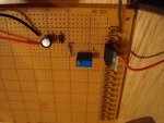
Put up a clear photo of both sides of the board, it will help diagnosis.
Regards rog8811
TheMonk
0
- Joined
- Aug 29, 2007
- Messages
- 750
- Points
- 0
rog8811
0
- Joined
- Jul 24, 2007
- Messages
- 2,749
- Points
- 0
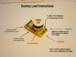
....and test it with this?
http://www.laserpointerforums.com/forums/YaBB.pl?num=1197651171
http://www.laserpointerforums.com/forums/YaBB.pl?num=1197651171
- Joined
- Jan 20, 2008
- Messages
- 1,724
- Points
- 0
If you powered it without a load, powered it with a shorted load, powered it with reverse polarity, or used too much heat in soldering it, you may have killed the regulator.
Otherwise, if you post a pic we can tell you if you wired it correctly to begin with...
Otherwise, if you post a pic we can tell you if you wired it correctly to begin with...
rog8811
0
- Joined
- Jul 24, 2007
- Messages
- 2,749
- Points
- 0
There's your problem....P2 led with a 1ohm resistor
- Joined
- Nov 7, 2008
- Messages
- 5,725
- Points
- 0
I can't tell any specifics about the circuit pathways from the front. If possible, give us a picture of the back as well. If the connections on the back can be seen, it will help with diagnosing your problem.
rog8811
0
- Joined
- Jul 24, 2007
- Messages
- 2,749
- Points
- 0
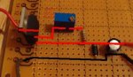
rog8811 said:Your circuit looks fine, change the test load.....
I noticed i soldered the pins on the 100ohm pot different so i solder them the same as your diagram and it still did not work.
- Joined
- Nov 7, 2008
- Messages
- 5,725
- Points
- 0

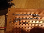
In this photo I've circled an area that seems to possibly have a solder bridge. Check closely and make sure that no solder is touching any adjacent contact strips.
