So I took what I learned from this build...
http://laserpointerforums.com/f50/first-build-complete-several-pics-84593.html
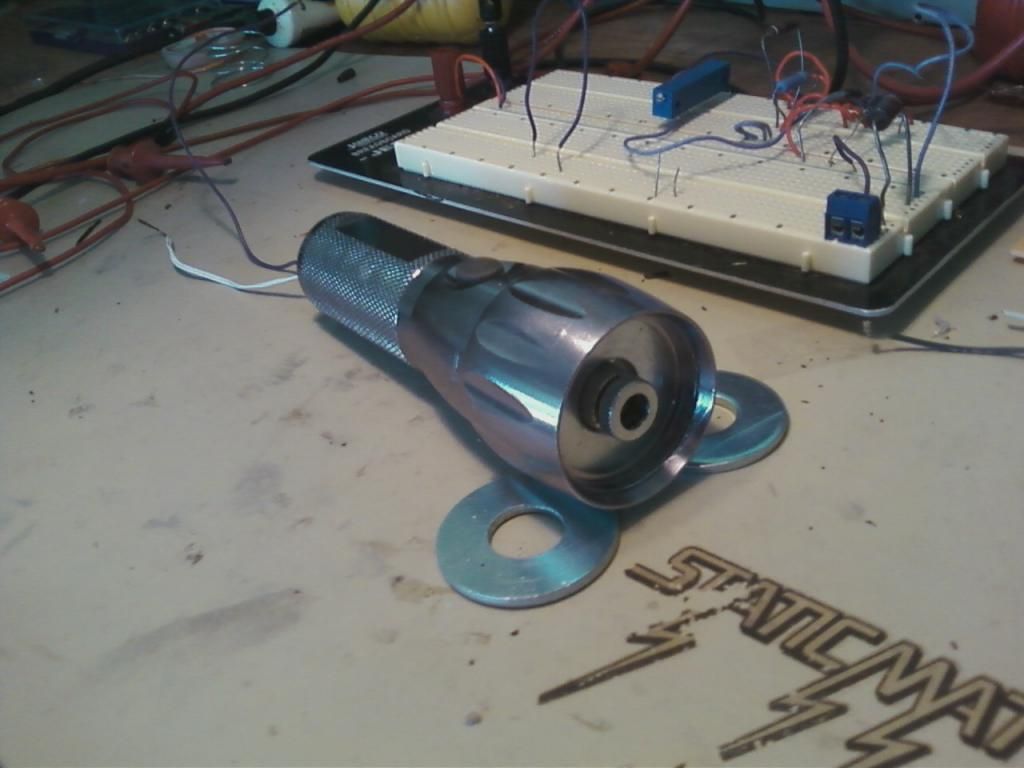
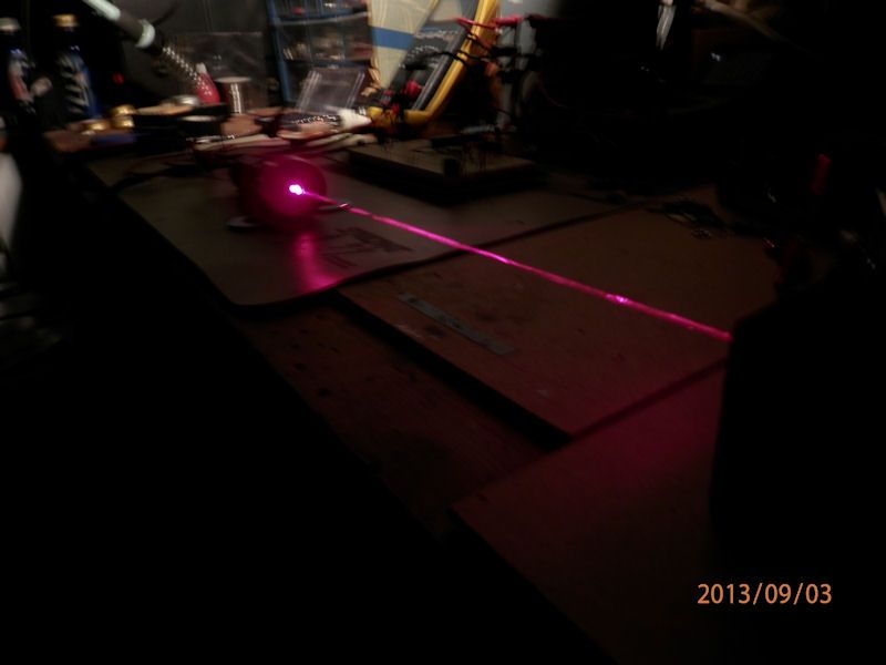
...and decided to make it smaller and put it in a old LED flashlight I had. I'm almost finished. I'm undecided on batteries so I ran leads out of the flashlight for testing. I have powered it at 6V and 7.2 V and it passed the "burn tape" test. I could probably power it from two CR123's or 10440's. Any suggestions?
I will post better pics later of the actual laser.
I actually killed the first LD I installed in this because I hot glued the washers in place. When I screwed on the top the wires got twisted too much and the LD pins fell off :yabbmad: When I received the new LD from DTR (thanks for the fast shipping) I did not glue anything and held the LD in place while I screwed the top on. This one seems to be a bit more powerful as focusing is not really necessary at close distances.
Components:
650 nm 300mW LD from DTR
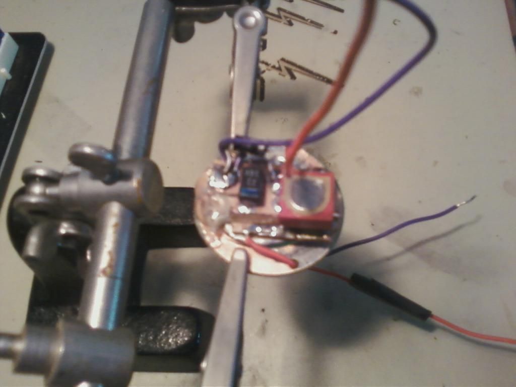
Homemade driver using LM1117 at 370mA with a penny for heatsink (bad pic). The LM1117 is under the red pot. I used a heat gun to solder the surface mount components to the board. Used a needle file to cut traces.
LED Flashlight housing

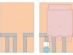
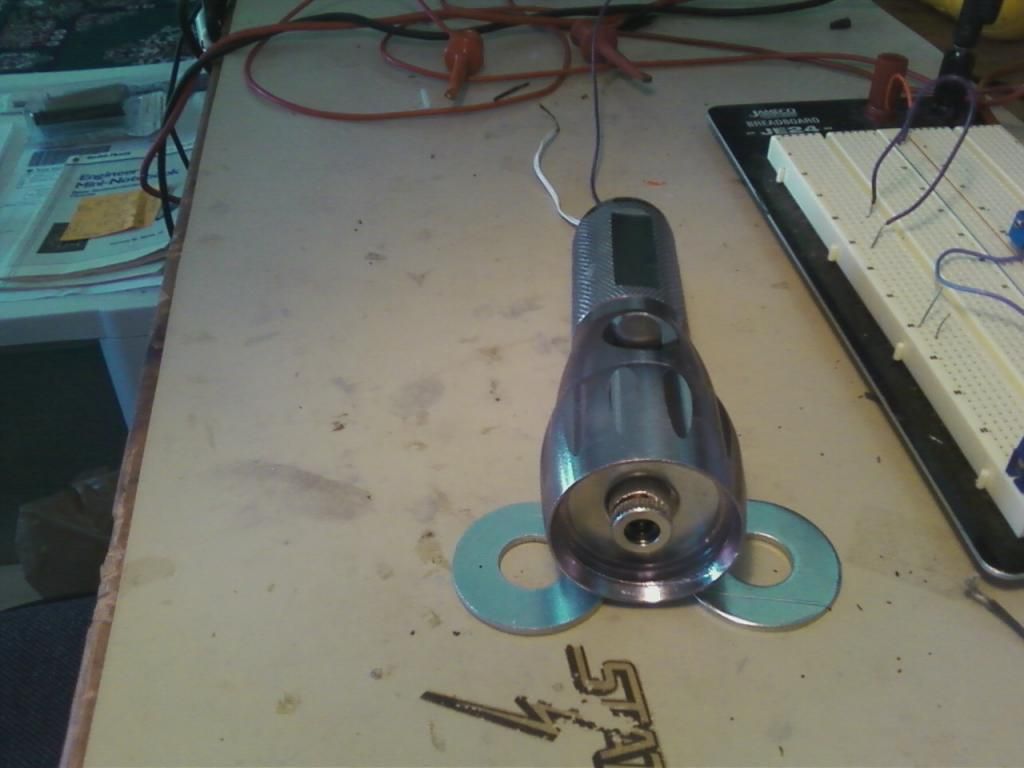
Several washers (see pic above)
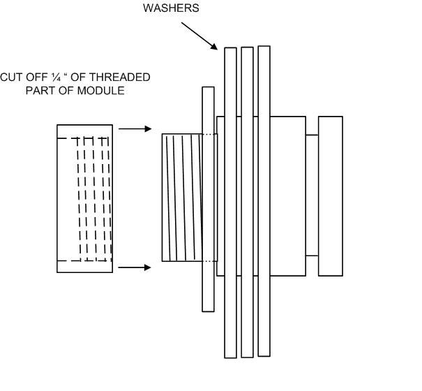
1/4 " of threaded part of module attached to LD housing with thermal paste between washers. I had already assembled it and forgot to take pic so I drew one. The threaded part of the module fastens the smaller washer to the LD housing. The larger washers fit perfectly into the flashlight housing. I used a bit of aluminum foil for a tight fit and added more thermal paste.
I used the existing power switch.
I will try to get some fog going in the garage and take some more pics. I'll use my real camera instead of the cell phone.
Sorry so long
More Pics:

http://laserpointerforums.com/f50/first-build-complete-several-pics-84593.html
...and decided to make it smaller and put it in a old LED flashlight I had. I'm almost finished. I'm undecided on batteries so I ran leads out of the flashlight for testing. I have powered it at 6V and 7.2 V and it passed the "burn tape" test. I could probably power it from two CR123's or 10440's. Any suggestions?
I will post better pics later of the actual laser.
I actually killed the first LD I installed in this because I hot glued the washers in place. When I screwed on the top the wires got twisted too much and the LD pins fell off :yabbmad: When I received the new LD from DTR (thanks for the fast shipping) I did not glue anything and held the LD in place while I screwed the top on. This one seems to be a bit more powerful as focusing is not really necessary at close distances.
Components:
650 nm 300mW LD from DTR
Homemade driver using LM1117 at 370mA with a penny for heatsink (bad pic). The LM1117 is under the red pot. I used a heat gun to solder the surface mount components to the board. Used a needle file to cut traces.

LED Flashlight housing

Several washers (see pic above)
1/4 " of threaded part of module attached to LD housing with thermal paste between washers. I had already assembled it and forgot to take pic so I drew one. The threaded part of the module fastens the smaller washer to the LD housing. The larger washers fit perfectly into the flashlight housing. I used a bit of aluminum foil for a tight fit and added more thermal paste.

I used the existing power switch.


I will try to get some fog going in the garage and take some more pics. I'll use my real camera instead of the cell phone.
Sorry so long
More Pics:


Last edited: