Welcome to Laser Pointer Forums - discuss green laser pointers, blue laser pointers, and all types of lasers

LPF Donation via Stripe | LPF Donation - Other Methods

Links below open in new window

ArcticMyst Security by Avery

Dilda Schematic!!!

Kage

0
Joined
Mar 5, 2008
Messages
285
Points
18
I got bored the other day and decided to try reverse-engineering the Dilda. The following PCB picts and the schematic are of the newer ones like those sold by O-like.com.

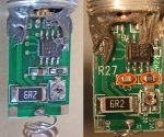
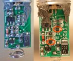
Here are the PCB picts with epoxy removed:


Dilda-Bottom.gif


Dilda-Top.gif


As near as I can determine, this is the schematic:

Dilda200.gif


I have included voltage readings for a 7V input and Current adjusted to 300mA for troubleshooting purposes.

I learned a lot about this device while doing this.
- The earlier models may not regulate properly, but can easily be updated by changing a few resistors to make them like the newer models.
- Once updated and working properly, R1 - the large 6.2 ohm resistor can be replaced by a piece of wire to allow the Dilda to run in regulation from two 3.0V batteries like the cheap green ones sold by DX
- The pot can be adjusted for over 400mA to the Laser Diode when the unit is working right.

Q1 and U1 part numbers are my best guess - I am ordering some to test ;)

Keep in mind this is a first try - there may be errors or omissions - :cool:

Edit:
Changed text above - I was calling the 6.2 - R27, but the schem shows it as R1. Oops :-?


Benm

0
Joined
Aug 16, 2007
Messages
7,896
Points
113
Nice work on the schematic!

Are the values in brackets those for the older, not-so-regulated versions of this circuit?
 
Joined
Sep 20, 2008
Messages
17,622
Points
113
I guess it needed someone with the time to do it...

Thanks for saving me all that work... ::)

Very nicely done... [smiley=tekst-toppie.gif]

Jerry
 

Kage

0
Joined
Mar 5, 2008
Messages
285
Points
18
Hey,

Thanks for the comments! :D

I hope this is useful to somebody. I was surprised that it seems to be built entirely around "discrete" components - must be cheaper for them or something.. :-?

Kurt
 

Kage

0
Joined
Mar 5, 2008
Messages
285
Points
18
Benm said:
Nice work on the schematic!

Are the values in brackets those for the older, not-so-regulated versions of this circuit?

Yes.

Sorry it's a bit hard to see the brackets because of having to convert DXF from Orcad to a picture format

On the newer models, R27 is underneath C5. If R27 is not there, I think it means you have the older version.

The other differences seem to just be resistor value changes.

oops, break time is over... :eek:
 
Joined
Feb 5, 2009
Messages
198
Points
18
Having known the frustration of tracing PCBs trying to determine the schematics what you did here is absolutely fantastic! ;D ;D ;D

The epoxy removal was clean and through too...although I have doubts whether the trim pot can still work ::)
 
Joined
Dec 21, 2008
Messages
1,223
Points
0
Kage said:
The earlier models may not regulate properly, but can easily be updated by changing a few resistors to make them like the newer models.

Hi, I'm afraid my electrical engineering skills are poor (actually, non-existent...  :-[). Could you please tell me if my recently-acquired Dilda has the newer regulation driver (pics are on the 5th row) - thx  ;)

Btw, what's with these "crushed-looking" pots...?!?
 

Kage

0
Joined
Mar 5, 2008
Messages
285
Points
18
Traveller said:
[quote author=Kage link=1234431525/0#0 date=1234431524]The earlier models may not regulate properly, but can easily be updated by changing a few resistors to make them like the newer models.

Hi, I'm afraid my electrical engineering skills are poor (actually, non-existent... :-[). Could you please tell me if my recently-acquired Dilda has the newer regulation driver (pics are on the 5th row) - thx ;)

Btw, what's with these "crushed-looking" pots...?!?
[/quote]

Yea, you can tell right away, because only the newest ones seem to have the component numbers silkscreened on the board.
What, crushed pot? You need rolling papers! ;D
 

Benm

0
Joined
Aug 16, 2007
Messages
7,896
Points
113
I've taken some pics of my old version and put them side by side with the new one.. and the changed components are marked.

PCB layout seems to be exactly identical, only the new one is silkscreened. C5 must have been a last minute addition since there is enough space to mount the components side by side at the lower left corner of the opamp.
 

Attachments

  • dx200pcb_1.jpg
    dx200pcb_1.jpg
    184.9 KB · Views: 422

Benm

0
Joined
Aug 16, 2007
Messages
7,896
Points
113
flipside
 

Attachments

  • dx200pcb_2.jpg
    dx200pcb_2.jpg
    184.1 KB · Views: 578

Kage

0
Joined
Mar 5, 2008
Messages
285
Points
18
Nice work Benm ! :D

C5 on the new board has a 1M resistor under it. I think their big mistake was leaving this resistor out on the early models - because it is a necessary DC feedback path (Rf) for the op-amp! ::)
 

Benm

0
Joined
Aug 16, 2007
Messages
7,896
Points
113
I suppose leaving it out just left the opamp as a comparator with near infinite DC gain.

I'm surprised it works as well as it does really, considering how close the inputs of the left opamp are to the ground rail. Surely it's rated as a rail to rail opamp, but in my experience working so close to ground remains tricky.

You wonder who's designing these circuits in the first place.. there are easier ways to create a stable current source, especially with some room for voltage regulation.
 

Kage

0
Joined
Mar 5, 2008
Messages
285
Points
18
Benm said:
I suppose leaving it out just left the opamp as a comparator with near infinite DC gain.

I'm surprised it works as well as it does really, considering how close the inputs of the left opamp are to the ground rail. Surely it's rated as a rail to rail opamp, but in my experience working so close to ground remains tricky.

You wonder who's designing these circuits in the first place.. there are easier ways to create a stable current source, especially with some room for voltage regulation.

Yes to everything you said. :cool:

My guess for the op-amp is a TI TLC2272 Rail-rail - Just now received some in the mail from Digikey. I have 2 bad Dilda boards, and one of them definitely has a bad Op-amp as well as both have blown PNP transistors. The test will be to see if I can repair these with the parts I just got. If so, then we can be pretty sure this is all correct. What clued me in to the op-amp was that one of mine has a suspicious symbol of texas stamped under a number 272...


Edit:
It worked! Both boards are working. :)
It is definitely the right Op-amp or at least a direct replacement, and the PNP I got, a 2SB1073 (20V, 4A, 1W, Mini-power) - seems to work okay as well. So, now I have 3 newer, working driver boards and an older "working" driver board, and no use for them, LOL. ;D


Top