Welcome to Laser Pointer Forums - discuss green laser pointers, blue laser pointers, and all types of lasers

LPF Donation via Stripe | LPF Donation - Other Methods

Links below open in new window

ArcticMyst Security by Avery

Connecting A laser Diode/Driver to a 7805 Voltage Regulator

Joined
Dec 11, 2011
Messages
32
Points
6
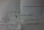
Okay so the multimeter was dying when i did the first set of tests. With the De-Energized or Energized on the 2 pin laser connector and Driver is 0.59v

When firing the laser its to hard to get a solid reading and it jumps because it only flashes for a second but I saw anywhere from 3-8v each time the trigger was pulled.
3.5, 5.8, highest was 8.7 i think and i could be wrong but it was never the same.

... now the catch. In order for me to break apart the lazser i had to compromise a working one so I had to get another red Diode. Worked fine for a few days but now you cant even see the laser. You can see the laser come on for a second but its not strong enough to see anymore. Maybe this is why I was getting different readings with the voltages?

I am currently unable to test the current because I'm trying to figure out how to measure the current. In order for me to measure it I have to use the red test probe and put it between or "break" the circuit. Do you really need the current readings as well?


Joined
Mar 2, 2011
Messages
692
Points
0
Your green diode has a driver right?
I would try to get a voltage regulator with an enabe pin on it.
Hook it up like this: enable to where the red diode used to be, vin to the battery, gnd to the battery gnd, and vout to the green driver.
 

benmwv

0
Joined
Sep 10, 2010
Messages
1,380
Points
48
So, we have established that the laser had it's own driver and that the board is supplying it with the batteries full voltage (with no current limiting, most likely) when the trigger is pulled.

Get one of these:
Voltage Regulator - 3.3V - SparkFun Electronics

Hook it up between the board and a 5mw green laser module (these are easily found on eBay, etc.) according to the pin-out in the datasheet. Ground goes to the black wire and negative connection on the module. Input goes to the red wire. Output goes to the positive connection or case of the green laser module (green lasers are case-positive).

Should work great.

I would definitely not use a 5v regulator for a 3v module. Many can't even handle the voltage of a li-ion battery.
 
Joined
Dec 11, 2011
Messages
32
Points
6
I cant seem to make my own red laser. I got a red laser pen and a regulator ( maybe ill try a different one ) The input pin on the regulator is +ve (red wire to PCB) The Ground pin on the regulator is soldered to the spring of the laser driver. There is another wire soldered from the ground pin to the -ve (black wire to pcb) The Output pin on the regulator was soldered to the casing of the laser pen.

I still dont think im doing this correctly. pin 1 (redwire) pin 2 (2 wires : 1 to ground, 1 to pcb) 3rd pin to the metal casing around the laser?

Maybe I do have the wrong regulator but if i cant hook up a standard red laser and get it to work i definitely cant get a green laser to work.
 

benmwv

0
Joined
Sep 10, 2010
Messages
1,380
Points
48
Try flipping the wires to the laser. The red laser is probably case negative.
 
Joined
Dec 11, 2011
Messages
32
Points
6
Alright Its been a while since I have posted and that's because I have been trying to get some information. Here is what I have found out so far, again all your help is appreciated.

Most of the equipment has these laser's in them.
Model #: JAT-LM 635 Visible Red Laser
Wavelength: 635nm +/- 5nm
Max Output: 0.8mW
Input voltage: 9.5v
Power Consumption: 160mW max
Manufactured by ... I think Iatco? Australia
Melles Griot Red Laser Assembly (05 ARR 006/9026-01001/2/3/4

There is a Transistor on the board that looks just like the 7805 regulators (9928 MTP 3055a) if this piece is taken off the Laser will not work. So however the mechanics of the board work that chip on the PCB has something to do with it.

I told you in an earlier post I bought another Diode and connected it to an existing driver. That diode burnt out so I bought another one, but now I have schematics for the driver. I cannot read schematics so maybe you guys can help me out on how to put this thing together.

Here is the schematic below..
 

Attachments

  • schematic 1.jpg
    schematic 1.jpg
    21.7 KB · Views: 1,482
Joined
Dec 11, 2011
Messages
32
Points
6
Is this what the schematic is showing me? Would this work or does it even make sense? I don't know how to read schematics :-(
 

Attachments

  • layout.png
    layout.png
    8.7 KB · Views: 3,986

rhd

0
Joined
Dec 7, 2010
Messages
8,475
Points
0
I think your best bet is to send this to someone in your country, have them do the mod on one gun, and provide you with an easier explanation for how to do the rest on your end. They might even pop together the parts into a simple kit or PCB.
 
Joined
Dec 11, 2011
Messages
32
Points
6
I cannot send the gun anywhere. This is for a place I work and the equipment is expensive. Never mind trying to get the green lasers firing I just want to know how to Hook up a standard RED LASER DIODE to a 7805.

Don't worry about what the voltages are, what the current is. I have given all the information I can. Supposedly this works I just need to know how its done, either it works or it doesn't. After putting the thing together it didn't work so im just asking if it's a fault on my part from not understanding or its there instructions.

I have posted pictures of what my setup looked like but i got no feedback. That's okay though I don't expect help from anyone Im just glad that you guys helped me as much as you could. If anyone has any additional information that would be awesome.
 

rhd

0
Joined
Dec 7, 2010
Messages
8,475
Points
0
I cannot send the gun anywhere. This is for a place I work and the equipment is expensive. Never mind trying to get the green lasers firing I just want to know how to Hook up a standard RED LASER DIODE to a 7805.

Don't worry about what the voltages are, what the current is. I have given all the information I can. Supposedly this works I just need to know how its done, either it works or it doesn't. After putting the thing together it didn't work so im just asking if it's a fault on my part from not understanding or its there instructions.

I have posted pictures of what my setup looked like but i got no feedback. That's okay though I don't expect help from anyone Im just glad that you guys helped me as much as you could. If anyone has any additional information that would be awesome.

The challenge is that this question (how to hook a red diode up to a 7805) doesn't really have an answer, because it's not something you would do. Or at least, I can't see why you would want to, or what you'd be trying to accomplish.

It's like saying "How do you connect a Ford Taurus to a computer PSU?". It doesn't make sense inherently. It's the same here. A 7805 is a 5V voltage regulator. There's no obvious purpose for connecting this to a diode. No red diodes require a 5V regulated input, so your question just doesn't have an answer. There is no "way".
 
Joined
Dec 11, 2011
Messages
32
Points
6
Alright this is the first response that I have seen or maybe I overlooked it that says this makes no sense. That is awesome because now i will stop trying.

This is just what was in the instructions so I was trying to make it work. When the trigger is fired its Firing off 9.6v so its burning out all the diodes i put in. I do not know how to build my own Laser Driver. You guys could show me if you want :)

I posted schematics and what i thought it meant but i guess that didn't make sense either. So can I ask you one more question?

If i take a laser pen/pointer. Where do i connect the red and black wires? Do i put the black wire on the spring? then where does the red wire go.

I tried a few variations and it resulted in smoke.

BTW I just have to say, RHD.. Thank you for all your patience I know its not easy dealing me when i fire off all these questions without understanding what im actually doing. Thank you :)
 

rhd

0
Joined
Dec 7, 2010
Messages
8,475
Points
0
Here's how to do it - build this driver:
ddl.jpg


It's super easy. You'll need to know the proper current your diode requires.

Q: What diode are you using?
 
Joined
Dec 11, 2011
Messages
32
Points
6
Its a red diode that I bought from the local electronics shop. The only thing it came with was that wrinkled schematic (posted picture in earlier post) that I was not supposed to take. The only person who was there at the time was unable to tell me specs on the particular diode. There was just the Schematic sheet in the bin so i took it. It just shows me the parts that i need for the diode with 1 being 3.0ohm resistor.

Thank you for showing me this still faced with one little issue.. Bad at reading schematics. Trying to learn though

I understand the LM317 connecting to the resistor. Im assuming the +/- leads connect to the +/- on the diode. C1 is that a capacitor?
 

rhd

0
Joined
Dec 7, 2010
Messages
8,475
Points
0
Its a red diode that I bought from the local electronics shop. The only thing it came with was that wrinkled schematic (posted picture in earlier post) that I was not supposed to take. The only person who was there at the time was unable to tell me specs on the particular diode. There was just the Schematic sheet in the bin so i took it. It just shows me the parts that i need for the diode with 1 being 3.0ohm resistor.

Thank you for showing me this still faced with one little issue.. Bad at reading schematics. Trying to learn though

I understand the LM317 connecting to the resistor. Im assuming the +/- leads connect to the +/- on the diode. C1 is that a capacitor?

I'm sorry to say that it will likely be impossible to drive this diode without specs. You'd be shooting in the dark (pun intended). I would also note that I *doubt* you bought a diode. You probably bought a module, or at least a diode in a housing with a lens. If you just purchased a diode, I think you wouldn't have found it in a "bin" (because diodes are about the size of a peppercorn.

I think you'd be doing yourself a favor to grab one of these:
635nm 5mW laser module 3.2VDC adjustable lens 635 nm | eBay

5mW of a highly visible RED, should be safe at 5mW, and you know the specs. It needs 35mA of current, so build the driver I suggested, perhaps to be conservative at like 30mA. That implies a resistor of around 42 ohms, and 1/8th Watt should be fine.
 
Last edited:
Joined
Dec 11, 2011
Messages
32
Points
6
See im learning.. You are right, I thought that whole piece was the diode/driver. It does have a lens and a housing around it. I posted a picture of it already. Its that little bronze 3pin thing that i connected to an existing driver.

I will order that piece that you suggested and TRY and build your driver. Thank you so much for your help.. But I still cannot read schematics :-/

is C1 a capacitor in your diagram? I understand the LM317 connects to a resistor then the laser module but what is c1?


Top