

- Joined
- Apr 2, 2009
- Messages
- 356
- Points
- 0
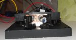
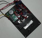
This is my first laser module, I have been building personal pointers for a little while and I feel I have enough practice to get into the scanning world. I am getting ready to build a couple more modules and put them all into one projector.
Diodes: 2x 150mW CW rated 642nm info here: World's First 642nm 150mW Laser Diode Launched by Photonic Products
Mounting: Diodes are mounted in custom copper housing placed in copper blocks with clamping screws to allow for rotation to dial in polarization
Lens: AR coated for 600-1000nm single element lens in custom brass assembly
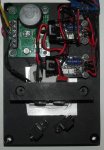
Drivers: Dual Flexmods set at 100mA idle and 320mA with modulation
Cooling: TEC cooled to -10°C and temperature controlled with a Die4Laser TEC controller
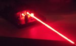
Output: 150mW after Lens at each laser and 293mW after optics from Knife Edge combination
Polarization: Horizontal
Everything is electrically isolated, the copper clamping blocks are clear coated so they are not contacting each other.
This module wasn't built with space in mind, but my next ones will be. I plan on building another one with dual 650 DVD diodes and combining these two reds using PBS after both knife edged modules. I will also repeat this once more with two 12x blu-ray diodes combined with a PBS attempting to get 600mW blu-ray with a reasonably decent life on them. I am about to order a 300mW 532nm module and a 100mW 473nm so this scanner should be pretty decent when completed. All analog modulation of course.
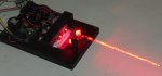
Smoke was used in this photo session since I didn't have a tripod to mount camera and do long exposure shots.
I didn't have my L wrenches to adjust the mirrors so the beams aren't aligned. Plus those mirrors are just mock up mirrors, I will replace them with clean ones when I get them in the mail.
Thanks for checking this out, comments and criticism are welcome.
Diodes: 2x 150mW CW rated 642nm info here: World's First 642nm 150mW Laser Diode Launched by Photonic Products
Mounting: Diodes are mounted in custom copper housing placed in copper blocks with clamping screws to allow for rotation to dial in polarization
Lens: AR coated for 600-1000nm single element lens in custom brass assembly
Drivers: Dual Flexmods set at 100mA idle and 320mA with modulation
Cooling: TEC cooled to -10°C and temperature controlled with a Die4Laser TEC controller
Output: 150mW after Lens at each laser and 293mW after optics from Knife Edge combination
Polarization: Horizontal
Everything is electrically isolated, the copper clamping blocks are clear coated so they are not contacting each other.
This module wasn't built with space in mind, but my next ones will be. I plan on building another one with dual 650 DVD diodes and combining these two reds using PBS after both knife edged modules. I will also repeat this once more with two 12x blu-ray diodes combined with a PBS attempting to get 600mW blu-ray with a reasonably decent life on them. I am about to order a 300mW 532nm module and a 100mW 473nm so this scanner should be pretty decent when completed. All analog modulation of course.
Smoke was used in this photo session since I didn't have a tripod to mount camera and do long exposure shots.
I didn't have my L wrenches to adjust the mirrors so the beams aren't aligned. Plus those mirrors are just mock up mirrors, I will replace them with clean ones when I get them in the mail.
Thanks for checking this out, comments and criticism are welcome.
Attachments
Last edited:


