Welcome to Laser Pointer Forums - discuss green laser pointers, blue laser pointers, and all types of lasers

LPF Donation via Stripe | LPF Donation - Other Methods

Links below open in new window

ArcticMyst Security by Avery

Knife edge followed by expander? Anyone try that here?

Joined
Jan 29, 2014
Messages
12,031
Points
113
Another thing you could do is just stack up the knife edging only in the narrow axis, achieving a stack 50-80mm tall, and then correct the beam with cylindrical optics + prism pairs in the wide axis to form a "square" beam of the target size.

Like this ¦ one on top the other? How do I stack them that way, are the diode holders elevated from one to the other to do so? My thought is mirrors can't align them that way or they would end up shooting off in different directions due to having an angle, or not flat to one another, that they can only correct minor errors, that physical stacking of the diode height is needed to achieve this, correct?

Bionic, can you help me understand this online lens diameter to wavelength divergence calculator: US-Lasers - Beam Divergence Calculator ?

I don't see how this calc. can really give the divergence, being the structure of the diodes themselves determines much too. Maybe this assumes single mode?
 
Last edited:


Joined
Dec 9, 2011
Messages
221
Points
28
Another thing you could do is just stack up the knife edging only in the narrow axis, achieving a stack 50-80mm tall, and then correct the beam with cylindrical optics + prism pairs in the wide axis to form a "square" beam of the target size.

This may be the best approach if you dont want to mess with PBS. Stack like ----. then expand the slow axis with cylinders. A guess would be about 16X expansion if using G2 lens. You wont be able to get this much expansion with prisms. This should give a fairly square beam profile of 12-16mm to send to the spherical expander. Also, the divergence should be fairly close. Maybe a bit tighter on the 16X expander axis.
 
Joined
Jan 29, 2014
Messages
12,031
Points
113
OK, I understand, stack them horizontally, or vertically and then correct in the opposite axis to broaden the slow axis. I don't know if I can find lenses to do 16X very easy, any suggestions?

thanks!
 

diachi

0
Joined
Feb 22, 2008
Messages
9,700
Points
113
The reason for using prism pairs instead of round optics is fairly simple in this case:

The diode as an output pattern that resembles a narrow line, which at a distance through regular optics becomes a wide line perpendicular to that narrow line. Prism optics only correct in one direction while round lenses correct in all directions at the same time.

What you are actually doing with a prism pair is building a beam expander that only acts in the direction the line output is narrow in. The goal is to expand the beam in that direction to match the other axis resulting in a more or less square beam profile at large distance.

Cylindrical lenses only correct on one axis too, so it has the same effect has a prism pair, although each has it's drawbacks and benefits.
 
Joined
Jan 29, 2014
Messages
12,031
Points
113
So far, it appears I can get as much as 6X from a anamorphic prism pair:

0000142-anamorphes-prismenpaar-300.jpg
 
Joined
Dec 9, 2011
Messages
221
Points
28
At 6X with prism the losses will be huge.

Edmunds has cylinders. I think the -12 is the shortest FL they have. -6 would be better that way the expander is not really long.

The truth is.... you will have a very low divergence beam even before the spherical expander.

Actually, you could probably do it with less optics by using different FL - lenses for each axis and 1 spherical lens at the output.
 

Gabe

0
Joined
Jan 10, 2015
Messages
1,147
Points
83
I'm late to the party and you e probably moved on from the idea Alaskan, but here's a quad diode knife edge with a beam expander, made by Tunedcavitylasers. So it has been done by someone: http://youtu.be/s7iUZ-zhuVM
 
Joined
Jan 29, 2014
Messages
12,031
Points
113
I could reach 10W with what I'm planning, but green :)

Thanks for sharing that, cool to see someone else has built such a monster. I plan on building a lower divergence one with a much wider beam. I put 4 watts of 532nm through a 12 inch diameter lens once, after expansion of course, and it was awesome to see that tunnel of light pierce into the darkness to became a sharp point in the far distance.

1e5b2be7-6084-434c-afed-40f6e5c657e9_zpsvdvrim9u.jpg
 
Last edited:
Joined
Oct 26, 2007
Messages
5,438
Points
83
This may be the best approach if you dont want to mess with PBS. Stack like ----. then expand the slow axis with cylinders. A guess would be about 16X expansion if using G2 lens. You wont be able to get this much expansion with prisms. This should give a fairly square beam profile of 12-16mm to send to the spherical expander. Also, the divergence should be fairly close. Maybe a bit tighter on the 16X expander axis.

No, I meant the other way around: you stack up in the slow axis and correct the fast axis. That way you can stack them as high as you want the final beam diameter, and then match that with your correction. It'd look like:

Code:
-----------------  correction   -------
-----------------               -------
-----------------      -->      -------
-----------------               -------


OK, I understand, stack them horizontally, or vertically and then correct in the opposite axis to broaden the slow axis. I don't know if I can find lenses to do 16X very easy, any suggestions?

Once you have both axises collimated and the beam output "square" with matching divergences, can't you just use a regular set of lenses at that point?

Remember too that prism pairs only change the beam diameter of an already collimated beam, so you need to use them after the cylindrical lens correction. The prisms will still affect the divergence, but most of the axis correction still needs to be done by the lenses.

If you want to do some lens calculations, try using ABCD matrices. Here's pretty decent site. Note that their calculator uses radians for the angle, not degrees. It may not produce perfect results due to the assumptions about lenses the calculations make, but can give you ballpark figures based on the optics.
 
Joined
Dec 9, 2011
Messages
221
Points
28
No, I meant the other way around: you stack up in the slow axis and correct the fast axis. That way you can stack them as high as you want the final beam diameter, and then match that with your correction. It'd look like:

Ok. I guess I misunderstood. At the end of the day accomplishes the same thing. Your way needs longer spherical expander mine needs longer cylindrical correction. By longer I mean takes up more space.

I still believe the best way is to use a different power negative cylinder lens for each axis and a spherical positive lens for the output. Less over all optics and space needed in total.

Also, I think stacking the way I describe will give the most symmetrical beam with 4 diodes. 4 stacked 1w greens with g2 will be aprox 14mm long. A 12x expansion of the FA will be about 14mm wide. The divergence will be around .3mrad both ways. (these are approximations)
 
Joined
Jul 10, 2015
Messages
9,907
Points
113
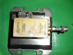
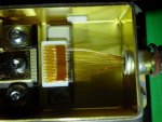
This old 808nm Coherent 12W laser has 18 emitters, each I think has a tiny FAC lens then a fiber that combines all 18 LD's into 1 output.
I thought wave front matching was needed to do this, or are they just 18 beams in a cluster.
I have seen fiber combiners that combine 2 laser sources, I thought the wave fronts had to be matched. But this one is just power it up and it all travels down a fiber for miles as these are old communications lasers. If the output was focused straight out of the output aperture would you have 18 dots in the farfield or 1 ?
Could a concave FAC type lens be used with our multimode diodes to square up the beam and then feed into fibers to make a bundle that could then be expanded to a desired diameter of beams and focused at the far field?
I suppose our diodes would need to be decanned to catch the output close to the emitter and the right tiny cylindrical lens would be need to square up the output by shaping just one axis?
I know this seems like more work but the final beam quality could be fantastic.
 

Attachments

  • SANY0290.JPG
    SANY0290.JPG
    180.5 KB · Views: 144
  • SANY0289.JPG
    SANY0289.JPG
    210.9 KB · Views: 190
Last edited:
Joined
Dec 9, 2011
Messages
221
Points
28
I have seen some combiners where the fibers are just epoxied in a ferrule and polished. This would give an image of a bunch of dots in the far field.
 
Joined
Jul 10, 2015
Messages
9,907
Points
113
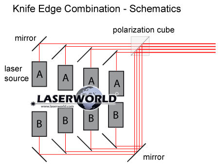
Thanks everyone, much to consider, thinking of adding more diodes :) for a total of up to 10 but combining 8 would make more of a square if using a PBS to combine two rows of four knife edged diodes and then expand that. I still don't know for sure if having half of the diodes at different heights is required to do that or not yet, is that required using a block like this?
d46f7f37829e4e28844cd206b_large.jpg


But from what I gather, doing the PBS method of combing the output from two blocks like that would cause half of the diodes to be in one polarity, the other half another polarity which throws out the simplicity of expanding all of one polarity together. I am still completely open on how to build this thing.

knife-edge-combination_-_schematics.gif


I have a 808nm FAP, and the fair field is definitely a bunch of closely spaced dots in the shape of a disk.

I expected it would be, but that's a workable arrangement. I have had 10 of the old single mode 660's on articulated mounts arranged into a cone to a point, each focused to infinity to begin with, then using a double concave and a regular double convex I could adjust the beam spacing in the cluster and the distance of the focal point.
Of course the further the focal point the larger the starting diameter is needed.
I have done the same thing as your green beam expansion with the m-140 and 7875 diodes by catching the raw output at a wider point about 2-2.5 inches from the diode with a pair of 40mm lenses in a slider that allows me to extend my fireworks fuse lighting range by 500% over the 3 element lens.
But with these multi modes I'm afraid some beam shaping will be needed prior to stacking to get a quality result. That's why I keep waiting for the next bigger single emitters LOL.
Planters is good at beam combining and does beautiful work, have you watched any of his videos?
https://www.youtube.com/user/TechIngredients
 
Joined
Jan 29, 2014
Messages
12,031
Points
113
Now i'm wondering how to beam shape each diode b4 stacking while keeping everthing small. No clue ATM, have to do some searching for examples. I've watched a couple of his video's, tks for link, will watch more
 
Joined
Jul 10, 2015
Messages
9,907
Points
113
Now i'm wondering how to beam shape each diode b4 stacking while keeping everthing small. No clue ATM, have to do some searching for examples. I've watched a couple of his video's, tks for link, will watch more

I don't mean to over complicate things for you, it just depends on if you want to seriously concentrate energy or just have a really brilliant spotlight.
Just knife edging can be fun.
It's a very old video of an A series block and knife edge + lens ripped straight out of a unit and stuffed into an Omni directional head. You have probably seen this before but it would be incredible in 520nm.
https://www.youtube.com/watch?v=lpY5TocaRM0


Top