Welcome to Laser Pointer Forums - discuss green laser pointers, blue laser pointers, and all types of lasers

LPF Donation via Stripe | LPF Donation - Other Methods

Links below open in new window

ArcticMyst Security by Avery

TTL laser diode driver

Joined
May 24, 2009
Messages
53
Points
8
im looking for the best way to set current and volts for my ttl driver. it is a diy poject and i got confused over in the laser torch area as how to set my current to the diodes i plan on using "just fry'd one ttl driver good thing it was only 5 bucks"

this is what i have :

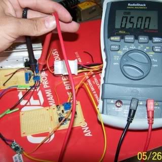
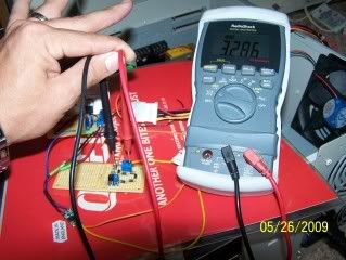
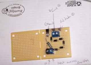
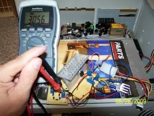
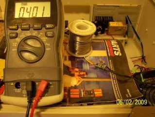
Computer power supply output 4.93v wired to a homemade Adj Lm317
voltage regulator tuned to an output to 2.83v as directly tested with digital multimeter for volts. The curcuit is similar to this:
voltage-regulator.png


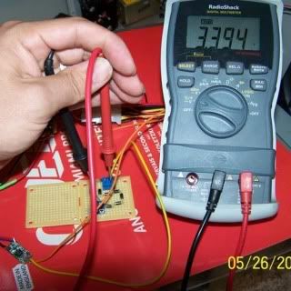
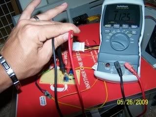
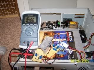
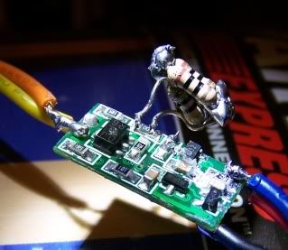
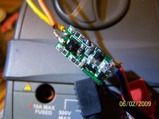
This 2.83v is fed to my constant current driver:
2009510231338925.jpg


I then tested the output of the constant current driver for voltage with multimeter ( 2.8v) Not much of a drop but no load just multi meter.


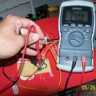
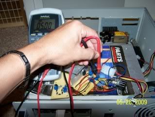
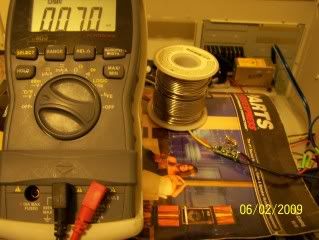
Next i adjusted the current pot to output of 180ma (no dummy load) just meter.

Questions:

1. Does my current needs to be adjusted while using a dummy load?
suppose to supply up to 600ma but i cant get past 180ma

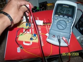
2. is the diode geting 2.8v or actually less ? as i have measured
no voltage drop. But then again im not measuring things correctly.

i tried to supply my driver with 5v I got more current but i killed it LOL.

If anyone can suggest a better ttl driver for red diodes let me know.

Any help is greatly appreciated
banghead.gif


Thanks in advance
dudley


Joined
May 4, 2009
Messages
5,443
Points
113
setting up I

Howdy yes you need a dummy load on there. use 4 plain diodes like 1n4004 and a 1 ohm resistor in series as a dummy load. you can then measure the voltage across the dummy load . and the current can be measured by putting your vom on millivolts and connect across the 1 ohm resistor each millivolt you read is the milliamps being drawn by the load.

Best Regards :yh: Pyro...
 
Joined
Jul 24, 2007
Messages
2,749
Points
0
I am getting the feeling of de-ja-vu, I am sure I have said what I am going to say now.....before...

If you are using an LM317 as per the drawing you will get constant voltage, you need to measure what that voltage is under load, use a test load as described above by FP.
To be sure it is doing the right thing you need to adjust the input voltage, you can go up to 12v if you want it will only heat up, the important thing is that the output voltage should stay exactly the same no matter what input voltage is applied....
To connect it up to the drivers you will need to know the overhead voltage of the driver circuits and add that to the voltage needed by the laser diode you are using, that is the voltage your LM317 needs to provide. (I am guessing that your computer PSU is not giving enough volts.... unless your drivers are boost and buck type, IE Lava drives).

I hope that helps.

Regards rog8811

EDIT..... I am not going mad, I did already answer this here....http://www.laserpointerforums.com/laser_pointer_forums_3/forum/showthread.php?t=40140&page=2
 
Last edited:
Joined
May 24, 2009
Messages
53
Points
8
I did some adjustments but still not adding up. driver is suppose to be capable of 500ma but cant get over 180ma without it getting hot. and then when i back test the volts input to the driver it exceeds 6v and driver can only hold 5v in. below are some pics to show what i got.

Here i have changed input to LM317 curcuit from 5v to 12v and adjusted to max recomended of 5v drive for diode driver. this should eleminate any input power problems unless this circuit is uncapable of the 400ma diode drive + curcuit requirements. Dummy load is attached for all measurements. 4 diodes for 650nm open can simulation.

5v.jpg


Here i tested for voltage drop 3.394 measured at dummyload.
5.00v subtract the measured 3.394v= curcuit voltage drop of 1.606v

339v.jpg


But this is to much for my red can diode? my target is 2.5v @400ma
so my max volt in should be 2.5v "diode requiremet"
+ 1.6v "volt drop"
--------
= 3.6 correct ?

My next pic is the measured Millivolt at the resistor to show drive current of 170ma
170ma.jpg


this is about the max i could get from the driver. I assume my problem is that my LM317 supply is not adequate to drive this curcuit to the needed 400ma or i need to change resistors on the driver " not easy all surface mount LOL. i guess i could piggy back"

Please let me know if i am doing anything wrong in my measurements
 
Last edited:
Joined
May 24, 2009
Messages
53
Points
8
i did adjustments to lm317 outout of 4.1v
100_4129.jpg


then measured the voltage out the diode driver:
100_4130.jpg


still shows over 3v ??? must be constant current driver ?

next i measured current in mv at the dummyload
100_4131.jpg


current did drop abit to 112.5ma

not sure whats goin on. any help greatly appreciated
 
Joined
Dec 23, 2008
Messages
3,948
Points
63
I don't see your dummy load in any of the pics. you put the dummy load on your driver in place of the Laser Diode. then set your multi meter to milli volts in the appropriate range. then put your multimeter leads across the 1 ohm resistor. there is a link in rog8811's signature. it is pretty simple. good luck. and make sure all your diodes are in the correct direction
 
Joined
Sep 20, 2008
Messages
17,622
Points
113
He's not using a Dummy Load... he is using the DMM as the load...:thinking:

Jerry
 
Joined
May 24, 2009
Messages
53
Points
8
FIY...my dummy load is the bottom board pictured here:
dummyload.jpg


the top board is the lm317

i did same test with different driver and got good results.

5 volts into driver:
c__voltin.jpg


volts out of the driver at the dummy load:
c__voltout.jpg


set current at dummy load: ttl on high
c__on_current.jpg


idle current was set to 40ma active current was set to 400ma

i then eliminated the lm317 board and connected driver directly to 5v computer supply, checking everything one more time.

I have concluded that the first driver i tried needs values changed on board to reach above 180ma.
 
Last edited:
Joined
May 4, 2009
Messages
470
Points
28
What Value did you change on that board. I'm having the same problem. I changed the 5ohm resistor for hi/low to 1.8ohm but I still only get 230ma out of it supplying 4.5v in.
 
Joined
May 24, 2009
Messages
53
Points
8
change resistor

hello.

i did pumped about 7 volts in it and it got very hot. I was tryin to get 5v output but fried a lead on the board.

After repair with solid wire i found the answer...

i did some piggyback testing on the high resistor. It comes shipped with 10 ohm so i kept adding 10 ohm "paralleled" until i got a good current.

Final figuration was stock resistor + (3) 10 ohm resistors which was (2) ohms when measured .

With 5v input I measured current out at 408ma. and nothing was getting hot so thats good..

i plan to make some with a surface mount 2 ohm resistor if you want some resistors. they are super cheap in bulk but i dont need all of them.
 
Joined
May 24, 2009
Messages
53
Points
8
here are some pics to help.. i did not change the low resistor because there is no need yet.. as long as you stay below 40ma you should be good for blanking.

make sure you dont accidentally solder low resistor to the high resistor "like me" , if you do it will run hi ttl and loose your blanking. damn its hard to solder this with a 150w soldering gun :p
ohms.jpg

added mountain of resistors

low_ttl.jpg

at low ttl 7ma
hi_ttl.jpg


my target ttl high current 400ma~250mw open can diode i have on ebay for 20 free shipping:drool:

i should have my TEC cooled, dual diode mount for sale too. holds (2) axiz units and room for cube to combine. for total 500mw red :) 1.5" x 3"
 
Last edited:
Joined
May 24, 2009
Messages
53
Points
8
finished

not sure what you did wrong. did you change the low resistor and the hi resistor ?

i scrapped the driver with the burnt lead, removed a 1.5ohm resistor as swapped it for the high ttl resistor.. finished pics below, i hope it fits the axiz module.
aftermod.jpg
;)
 
Last edited:
Joined
May 24, 2009
Messages
53
Points
8
good luck on this step, you will never- NEVER get all of the driver board and wires in the aixiz unit. If you do i will call you DADDY LOL.

My solution was drill the back out with 3/8" drill bit and ensure your positive lead is not extending past the pcb (if it does it will short out).

Make sure your diode is solder straight to the pcb. I even cut a little off the pos leg to prevent it from touching other parts on the driver.

You must Carefully did i say CAREFULLY screw the back on or you will twist your pins off your diode..i did that too.

this is an extremely tight fit. i would go as far to say as it doesnt fit unless your really patient when doing this.

i ran it for a couple seconds for the pic but gets warm fast without heatsink. I would suggest tec cooling as i have my parts on order. should be here this week.

Glad i just got one more to do!


done10x20.jpg
 
Last edited:

diachi

0
Joined
Feb 22, 2008
Messages
9,700
Points
113
Very nice ! You bet me to designing and making one of these !

Did you use an optocoupler for the modulation ? Along with maybe a transistor ?


EDIT: Never mind, Looks like a Dual Operational amplifier.
 
Last edited:
Joined
May 24, 2009
Messages
53
Points
8
No, i dont know much about the driver except that it is a very cheap buy. I tried to get some information on the chip but they didnt say much. You know how those half english emails are LOL. They did say they will have a blu-ray version soon.


Top