Welcome to Laser Pointer Forums - discuss green laser pointers, blue laser pointers, and all types of lasers

LPF Donation via Stripe | LPF Donation - Other Methods

Links below open in new window

ArcticMyst Security by Avery

Simple Galvo set - Requirements & Possibilities?

Joined
Aug 11, 2013
Messages
105
Points
18
My apologies for this 3rd post in a row, but I think if I just keep editing no-one will notice since no "New Post" sign will pop up ;)

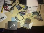
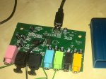
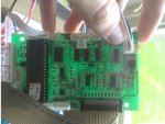
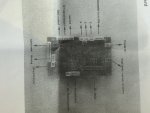
The galvo set I ordered (and have had for some time now) came with the mirror stuff, 2 drivers, power supply and a "Show Card". That last thing has a huge IC on it, as well as inputs and outputs all over, including ILDA, DMX and a dipswitch (10 switches). Due to this showcard, everything was plug&play, and the demo started playing. There's relatively OK documentation on DMX (if you know about DMX, I guess :) ), but none on ILDA. I know enough about ILDA (pin-out of the connector, min/maximum voltages etc) but I'm not sure how to get this showcard to accept it. The ILDA connector is connected to that card, but AFAIK all the dipswitch-combinations are reserved for demo's or DMX stuff. I mailed the vendor, and his reply was kinda cryptic:
If you want to use ILDA cable to provide input (ILDA , no t DMX or dip switch), you only connect to PIN25PIN. It is first for ILDA to work

use the input from the ILDA cable , others (DMX. aAUTO, SOND) are not work
I figured this meant that in order for the card to accept ILDA input, I'd just have to connect pin25 to the ground - I figured when it registers a ground it switches to that connector. That doesn't work however, so I figure it must be something else. Who's got an idea?
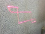
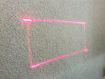
Edit: I've added some images that might help. Tilt your head 90 degrees ;)
 

Attachments

  • p1.jpg
    p1.jpg
    331.8 KB · Views: 165
  • p2.jpg
    p2.jpg
    366.6 KB · Views: 156
  • p3.jpg
    p3.jpg
    318.5 KB · Views: 182
Last edited:


Joined
Aug 11, 2013
Messages
105
Points
18
Try linking pins 4 and 17 together

I've had to partially disassemble it because I use the same desk for regular work, but shorting pins 4&17 indeed stopped the demo and a small LED labeled "ILDA LED" started glowing, so I'm pretty sure that worked. Now I also know what the interlocking pins are for ;) Thanks!
 
Joined
Aug 11, 2013
Messages
105
Points
18
Finally, good news! The last few days I've been at war with soldering the correction amps & laser driver. Apparently, the metal plate on the transistor is NOT there to provide good thermal contact to the heatsink (or maybe it is? :) ) but it's also the emitter, turning my heatsing into one huge emitter. Since the heatsink is large and rests on the print board - which is grounded on top - stuff doesn't work as you'd expect. Combined with wrong memories of Op-Amp numbering and potmeters where the right resistance falls within what seems to be 0.0001 degrees of turning (without realising this and just thinking something else must be broken), you can imagine what it's been like for me.

But now, finally, I got it to work!
https://www.youtube.com/watch?v=n25b9LHbokQ

Yeah... That's supposed to be a nice square. What's shown is 4 different files, using a sampling frequency of 5000, 10K, 20K and 40K. (Come to think of it, the last one is probably overkill :) ) As you can see, I've got a lot of tuning to do! I'll postpone that until I've attached some heatsinks to the galvo drivers though, they're running hot very fast. The last thing you see is actually a visualisation of some youtube-dubstep. I was surprised to find that the galvos actually also function as speakers, I could hear the music pretty well!

Apart from the galvo tuning, I guess I should also tune the correction amps better. (Captain hindsight tells me I should've used 10-turn pots after all)

However, I hate it when things people say in my welcome thread come true (something about spending money ;) ). Since I learnt that I can make PCB's at my uni, I'm considering "starting over again", but on a decent PCB instead of my soldering-attempts. That second version would have some blue and green as well. I first wanted to finish this project to 'well, it's working' so I know where the pitfalls are and I feel I can actually "plan" the whole next thing. Maybe not such a bad idea, since it'll cost me a bit more.

One more pic, and then it's time for a movie over here.

Edit: Right, I forgot to ask. While I should be able to solve the oscillations in the square by tuning, does anyone have any idea what the 'ghosted' images are? Sometimes I can also hear the mirrors turning when I provide no input. Could this be a case of ground loops, bad wiring, crosstalk, or whatever you can come up with? It doesn't always happen, and AFAIK my laptop is not outputting any other sounds when this happens.
 

Attachments

  • 800pix.jpg
    800pix.jpg
    338.6 KB · Views: 207
Last edited:

Scoots

0
Joined
Sep 25, 2009
Messages
47
Points
8
The galvo amps shouldn't need tuning, the problem is more than likely
your correction amp. Can you post some close up pics of your correction
amp and the circuit you used. Also what sound card are you using
 
Last edited:
Joined
Aug 11, 2013
Messages
105
Points
18
Soundcard: USB 6 Channel 5 1 External Audio Sound Card s PDIF | eBay
Also see attachment. Black is ground, green cables are for X, Y and laser intensity, soldered to the outputs that stay at DC level and don't go back to zero over time.

As for what amps need tuning: I'm fairly certain I fiddled (a little bit) with one of the tuning pots on a (x or y...) galvo drivers when I ran the demo weeks ago to see what happened. Then I realised that wasn't smart and left it at it. But you're right, that shouldn't have such an effect.

Other two attachments show the circuitry, all created after BenM's circuits posted in this thread (replaced opamps by 072s, since the shop didn't have the other ones).
Red = +15V, orange = -15V, blue = connections from potmeters (yes, 2 different types, had to look for spares) to opamps, black = ground, green = soundcard signal IN or ILDA out. Roughly speaking, left in the image is left in BenM's schematics.

Next time, I'm getting a PCB ;)

Tried to 'tune' the correction amps according to BenM's instructions, but due to the pots I settled when the values came within a few (20) mV from either 0 or 5V, depending on what was necessary at that point. The one for the Y-mirror ('middle circuit' in image) is even less accurate due to the 1-turn pot.
 

Attachments

  • SC.jpg
    SC.jpg
    147.4 KB · Views: 212
  • SC1.jpg
    SC1.jpg
    178.3 KB · Views: 163
  • corrampsclose.jpg
    corrampsclose.jpg
    193.4 KB · Views: 155
Last edited:

Scoots

0
Joined
Sep 25, 2009
Messages
47
Points
8
Did you set up the outputs of the correction amps to be 0v when no image is being displayed and +5 when there is ??
 
Joined
Aug 11, 2013
Messages
105
Points
18
Yup, I did. Decided to check again, and for some reason they were way off. While trying to re-calibrate, I noticed they're drifting: Where I had ~0V at no signal and ~5V at signal, after 5 minutes of playing I re-measured and it had gone to 1.1 (X) or 2.5 (Y) volts for no signal, and ~+-5.6 (X) or +-4.7 V for max signal.

Checked the tuning screws on the galvo drivers, and they are still sealed, so the only screw I've touched must have been the input scaling one, which isn't that of a problem.

After recalibrating, the square was much better, but clearly the vertical jump happens too early. Strange, because the code clearly has everything happen at the right time. (See plots) Edit: Looked at the figure again, it's not just the vertical jump being too early, there seem to be 2 jumps!. Interestingly enough, if I switch from 6 channel output to 4 channel output (I use 3 channels for X, Y and R atm) the square becomes much better! However, you still see the horizontal movements starts to 'brake' rather soon, while the vertical doesn't. (Based on intensity of the lines).

So,
* Any idea why the signal might be drifting? I've definitely connected to the right soundcard output ;)
* Any idea why 4channel output has better results than 6channel output? Can switch to 4 for now, but want more colors later on ;)
* Any idea why horizontal movement is brighter, even though distance is longer and every edge should have the same illumination time?

Thanks! :)
 

Attachments

  • plot.jpg
    plot.jpg
    21.6 KB · Views: 157
  • 6CH.jpg
    6CH.jpg
    179.8 KB · Views: 144
  • 4ch.jpg
    4ch.jpg
    181.3 KB · Views: 124
Last edited:
Joined
Aug 11, 2013
Messages
105
Points
18
Well, everything is on a brief hold for now. Using some rough tuning, I tried to get HE Laserscan working, which proved to be quite a hassle with missing EzAudDac.ini files (had to learn I needed them to start with). Then had problems with all signal seeming to be sent through one channel instead of three. Then noticed some wrong wiring (X, Y and R soldered to the wrong DAC pins for - say - Y, G and R or so), fixed that and then lost all signal.
Then somehow managed to break my red diode (don't worry, was a cheap one, but also the only one I had), and AFTER that found out the .ini file missed the following part:
[Channel Selection]
;Enter the desired output chanel number (1-8 only) of the signals:
X=1
Y=2
R=3
G=4
B=5
I=6

Adding that at least gave me back movement in the mirrors, although I'm not sure it's right yet (Horizontal and Vertical lines both make the Y-mirror oscillate). Maybe still some wrong channels, but can't really check that until I have a new laser, and since I'll be on holiday for 2 weeks starting next week...

Anyway, thanks for all the help I got so far, and

terminator.jpg


EDIT: For anyone wondering how this all ended, please see my thread for V2!
http://laserpointerforums.com/f47/laser-projector-building-phase-90283.html
 
Last edited:


Top