Welcome to Laser Pointer Forums - discuss green laser pointers, blue laser pointers, and all types of lasers

LPF Donation via Stripe | LPF Donation - Other Methods

Links below open in new window

ArcticMyst Security by Avery

Scanned images are waving

Joined
Aug 11, 2009
Messages
21
Points
0
I have a set of PT-30K galvos that still need to be tuned but that are producing decent, recognizable images using a soundcard DAC and HE Laserscan 5. The problem I am having is that all the images (test patterns, for example) look like they are being modulated by a sine wave at about 2 Hz. In other words, the images are "waving" up and down about 2 times a second but otherwise staying intact. I'm pretty sure that when I tested these same galvos a week ago, the waves were absent. I have a video if my explanation is unclear. Has anyone seen this before? Is it likely a galvo driver issue or DAC issue? Interference maybe?


This doesn't seem to be an issue that is addressed in any tuning guides, which discuss stationary issues like overshoot, undershoot, and constant image distortion. I couldn't seem to find any information on this, though I may have been using incorrect search terms. Thank you to everyone who has helped me get my first scanner to a point of near completion; you guys are awesome.


Joined
Nov 10, 2008
Messages
4,186
Points
63
Check the wiring and see if it helps. But do it. The projection on my set would stutter. After I rewired everything, all worked smoothly.
 
Joined
Aug 11, 2009
Messages
21
Points
0
Alright, it sounds like it might be the wiring, so I'll take a look at that and let you know how it goes.

Actually, it makes sense that this might be the problem, since I'm kind of confused about what is actually supposed to be grounded where. All my lasers have + and - modulation wires that are connected to the proper DB25 pins. Those - DB25 pins are also connected to the same ground as the laser power. My galvo drivers, however, have three modulation wires, +, -, and ground. Since all the - DB25 pins are already connected to ground, it seems like I'm supposed to connect two things to ground. Am I supposed to connect both the - and ground galvo driver modulation wires to the same DB25 pin, or do I leave one of the wires unconnected, or should I do something else? Thank you both.
 
Joined
Nov 10, 2008
Messages
4,186
Points
63
Only the galvos have a differential signal input. That means that the - of the X and Y galvos need to be connected to the respective DAC DB25 pins. And both X and Y grounds to the same ground which afair is pin 25. Since the laser inputs - are all connected to the same ground pin, you can either wire the laser inputs to the respective pins or on the ground pin.That's the difference between the scanners and the lasers. At least that's how most dacs are designed. Hope this helps. I'm 99% sure it's a wiring thing.
 
Last edited:

DJZ

0
Joined
Aug 27, 2008
Messages
270
Points
0
Alright, it sounds like it might be the wiring, so I'll take a look at that and let you know how it goes.

Actually, it makes sense that this might be the problem, since I'm kind of confused about what is actually supposed to be grounded where. All my lasers have + and - modulation wires that are connected to the proper DB25 pins. Those - DB25 pins are also connected to the same ground as the laser power. My galvo drivers, however, have three modulation wires, +, -, and ground. Since all the - DB25 pins are already connected to ground, it seems like I'm supposed to connect two things to ground. Am I supposed to connect both the - and ground galvo driver modulation wires to the same DB25 pin, or do I leave one of the wires unconnected, or should I do something else? Thank you both.

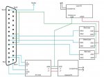
Maybe this will help?
 

Attachments

  • Simple ILDA.jpg
    Simple ILDA.jpg
    44.5 KB · Views: 1,987
Joined
Nov 7, 2008
Messages
5,725
Points
0
And both X and Y grounds to the same ground which afair is pin 25.

On Chinese galvo sets the X and Y channel grounds should be left disconnected. Only connect the + and - on the amp inputs. I should have added that in my last post lol.. All grounds EXCEPT the galvo amp inputs from ILDA. The galvo amp POWER grounds MUST be connected to the central ground.
 
Last edited:
Joined
Nov 10, 2008
Messages
4,186
Points
63
On Chinese galvo sets the X and Y channel grounds should be left disconnected. Only connect the + and - on the amp inputs. I should have added that in my last post lol.. All grounds EXCEPT the galvo amp inputs from ILDA. The galvo amp POWER grounds MUST be connected to the central ground.

I'm not sure about that. I was told otherwise. Really. Isn't the input differential on the galvos? If yes, the ground IS necessary, as far as my electronics knowledge tells me.
 
Joined
Nov 7, 2008
Messages
5,725
Points
0
110% sure. Ground is necessary on the galvo amp POWER connections, not the signal inputs. I had issues with smaller than normal scan angle until I disconnected the grounds on the signal inputs.. not sure why exactly. They are differential yes, but the signal comes in on only two wires, + and -.. I had to supply the ground from elsewhere, so I connected the input grounds to the central ground point. Doing so reduced my scan angle by at least 20 degrees, and the scanned imagery looked no better than with those grounds disconnected. Now I leave that connection disconnected on every Chinese scan set. The instructions that come with some of them even say to leave it disconnected..
 
Last edited:
Joined
Oct 26, 2007
Messages
5,438
Points
83
No, the differential inputs obviate the need for a common signal ground. You can think of one of the inputs as the ground for the other input. The reason differential inputs are used is that you don't need a common ground for all inputs. This is convenient when you have a lot of different signal inputs coming from different sources, where wiring things to share a common ground would be a pain, or if you want control of each ground reference. Phone lines do that because the signal has to go to all different locations where fixing a ground may not be possible.
 
Joined
Oct 26, 2007
Messages
5,438
Points
83
110% sure. Ground is necessary on the galvo amp POWER connections, not the signal inputs. I had issues with smaller than normal scan angle until I disconnected the grounds on the signal inputs.. not sure why exactly. They are differential yes.

It might be forming a ground-loop (i.e. why we should tie to a single ground point), which affects the amplifier's power supply. Not sure about the 2hz thing though. I thought it'd be at a higher frequency.
 
Joined
Nov 7, 2008
Messages
5,725
Points
0
Th "2hz" is actually a beat frequency.. what is happening is 50-60Hz line frequency is being superimposed on the image, which itself is being scanned at a certain frequency. The resulting beat frequency at which the image oscillates might appear to be only be around 2Hz.
 
Last edited:
Joined
Oct 26, 2007
Messages
5,438
Points
83
I did know it's a beat frequency, but wasn't sure how it ends up resolving to 2hz in the end. I guess it could be the image being rendered at ~30fps?
 
Joined
Nov 7, 2008
Messages
5,725
Points
0
No, the differential inputs obviate the need for a common signal ground. You can think of one of the inputs as the ground for the other input. The reason differential inputs are used is that you don't need a common ground for all inputs. This is convenient when you have a lot of different signal inputs coming from different sources, where wiring things to share a common ground would be a pain, or if you want control of each ground reference. Phone lines do that because the signal has to go to all different locations where fixing a ground may not be possible.

Differential signals also eliminate a few different types of noise/interference that can become problematic with long cable runs.
 
Joined
Aug 11, 2009
Messages
21
Points
0
Thank you for all the input. I won't have access to the scanner again until Friday, but I'm 95% sure that the problem is the connection of the galvo signal input to the ground pin 25. First of all, this pin is not connected to the common ground like the pins 18, 19, and 20 (for the lasers) are. According to the helpful diagram from DJZ, I could try connecting pin 25 to the common ground. However, since ElektroFreak recommends not having the galvo signal grounds connected on my particular galvos (PT-30K) anyway, I'll first just try disconnecting those from pin 25. I think this might have been the configuration I used a week ago when the waves were absent.
 
Joined
Nov 7, 2008
Messages
5,725
Points
0
Thank you for all the input. I won't have access to the scanner again until Friday, but I'm 95% sure that the problem is the connection of the galvo signal input to the ground pin 25. First of all, this pin is not connected to the common ground like the pins 18, 19, and 20 (for the lasers) are. According to the helpful diagram from DJZ, I could try connecting pin 25 to the common ground. However, since ElektroFreak recommends not having the galvo signal grounds connected on my particular galvos (PT-30K) anyway, I'll first just try disconnecting those from pin 25. I think this might have been the configuration I used a week ago when the waves were absent.

I would do the following:

1) connect pin 25 to ground.

2) disconnect Galvo signal inputs from ground.


Top