Welcome to Laser Pointer Forums - discuss green laser pointers, blue laser pointers, and all types of lasers

LPF Donation via Stripe | LPF Donation - Other Methods

Links below open in new window

ArcticMyst Security by Avery

First scanner build (eventual tutorial)

Joined
Nov 7, 2008
Messages
5,725
Points
0
Thanks flecom, I have to admit that you are a MAJOR reason as to why I am attempting to complete this project. I showed my girlfriend the pictures and videos from your 5 Watt RGB projector and we were both blown away! I am a computer programmer by trade and I think that creating a DIY scanner is the perfect hobby from me :)

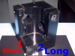
QUESTION: If you look at the photos I uploaded, you will see that the (el cheapo) SpaceLas 20K galvos have a 3-wire plug that will connect to my custom sound card DAC / correction amp. The only problem I see is that the correction amp only has TWO connections each for the X/Y galvos. Do I just use the IN+ and IN- on the galvo board or do I have to do something else? I read somewhere that I may need to connect a 4.7 kilo Ohm resistor to the ground. What ground, on the galvo or on the correction amp? I am not sure what to do here, all the galvos I have seen use 3-wires so I am sure someone has dealt with this issue before.

* As you can see from the last attached photo, I already have two heatsinked LOC red diodes and at 1 watt 445 diode ready to go. For now I am going to just get the 532nm going from my newly aquired +150mW analog before I purchase the dichros and PBS cubes for a full RBG scanner.

The correction amp was just purchased from Dr. Lava and I plan to upgrade the 9V DC-DC converter with one that supplies 12-15VDC which will (supposedly) improve the scan angles:
NKA0512SC Murata Power Solutions DC/DC Converters & Regulators

Any hints, tips, tricks will be greatly appreciated!

EDIT - Link to the documention for my SpaceLas PT-20K Galvos:
http://zimmtech.net/SpaceLasPT-20K.pdf

The reason the galvo amp has three connections is because they are designed to use differential signaling, which involves a signal that swings between both positive and negative voltages, typically a 10V peak to peak swing, +-5V. The three connections are +, - and ground. The sound card DAC provides single-ended signaling, which uses a signal that is DC, the waveform exists entirely in the positive region, between 0V and +9-10V. To apply a single-ended signal to the galvos differential inputs only requires that you apply the signal from the DAC to the + and - inputs on the galvo amps, leaving the ground unconnected or connected to an external ground source. By doing this the galvo amps will function perfectly with a single-ended signal with no loss of scan angle. Hope this helps!


flecom

0
Joined
Jul 25, 2010
Messages
303
Points
0
The reason the galvo amp has three connections is because they are designed to use differential signaling, which involves a signal that swings between both positive and negative voltages, typically a 10V peak to peak swing, +-5V. The three connections are +, - and ground. The sound card DAC provides single-ended signaling, which uses a signal that is DC, the waveform exists entirely in the positive region, between 0V and +9-10V. To apply a single-ended signal to the galvos differential inputs only requires that you apply the signal from the DAC to the + and - inputs on the galvo amps, leaving the ground unconnected or connected to an external ground source. By doing this the galvo amps will function perfectly with a single-ended signal with no loss of scan angle. Hope this helps!

this is the quick and dirty way, and how I do it too when I use my sound card dac... but the soundcard dac will always be outputting 0VDC on the inverting input, so it does affect scan angle...

galvos work and +/-10VDC input

http://www.laserist.org/StandardsDocs/ISP05-finaldraft.pdf

so a possible differential of 20VDC between the two rails... the soundcard will have a possible differential of 10VDC since the negative leg will always be at 0VDC or GND

if you want to be proper about it you would get a single ended>balanced driver like a DRV134 from Ti

http://focus.ti.com/general/docs/lit/getliterature.tsp?genericPartNumber=drv134&fileType=pdf

but as far as I know nobody does this
 
Last edited:
Joined
Nov 7, 2008
Messages
5,725
Points
0
this is the quick and dirty way, and how I do it too when I use my sound card dac... but the soundcard dac will always be outputting 0VDC on the inverting input, so it does affect scan angle...

galvos work and +/-10VDC input

http://www.laserist.org/StandardsDocs/ISP05-finaldraft.pdf

so a possible differential of 20VDC between the two rails... the soundcard will have a possible differential of 10VDC since the negative leg will always be at 0VDC or GND

if you want to be proper about it you would get a single ended>balanced driver like a DRV134 from Ti

http://focus.ti.com/general/docs/lit/getliterature.tsp?genericPartNumber=drv134&fileType=pdf

but as far as I know nobody does this

You're correct it can affect scan angle, but both 300EVIL and I have been able to increase the scan angle to the same as it would be if running differential simply by using +-12V DC-DC converters to power the correction amp circuit. Side by side with my FB3-XE, the scan angle from my soundcard DAC is identical. I had always been under the impression that the standard was +-5V, but it does clearly say +-10V.. so I'm not really sure where my discrepancy comes into play.. perhaps I'm missing something somewhere.
 
Last edited:
Joined
Jul 22, 2008
Messages
288
Points
28
The reason the galvo amp has three connections is because they are designed to use differential signaling, which involves a signal that swings between both positive and negative voltages, typically a 10V peak to peak swing, +-5V. The three connections are +, - and ground. The sound card DAC provides single-ended signaling, which uses a signal that is DC, the waveform exists entirely in the positive region, between 0V and +9-10V. To apply a single-ended signal to the galvos differential inputs only requires that you apply the signal from the DAC to the + and - inputs on the galvo amps, leaving the ground unconnected or connected to an external ground source. By doing this the galvo amps will function perfectly with a single-ended signal with no loss of scan angle. Hope this helps!

Thanks to everyone for all their help! From the ILDA specification that Flecom sent, I see that the galvos operate at a +/-10V differential. Does this mean that for the galvo to be in the neutral/middle position, the sound card DAC has to output 5V? Will I be missing half the range of my galvos using this setup? I notice that in the "tuning" section of the sound card DAC tutorial, each channel is supposed to be adjusted for a maximum of 5 volts. Am I missing something here?

You're correct it can affect scan angle, but both 300EVIL and I have been able to increase the scan angle to the same as it would be if running differential simply by using +-12V DC-DC converters to power the correction amp circuit.

I have already ordered Dr. Lava's correction amp but I plan to upgrade to DC-DC converter with the following:

> NKA0512SC Murata Power Solutions DC/DC Converters & Regulators
"I highly recommend replacing the DC-DC converter with one that supplies +-12-15VDC such as the part above. This is a drop in replacement for the correction amp board which will vastly improve the scan angle."

Will this bring my unit up to par with 300EVIL's version? I would have purchased his but I have found no documention on the unit. Just a couple of photos and he did not respond to my request to purchase.

PS - I promise I will keep my questions to a minimum until I get everything together ;)
 
Last edited:

flecom

0
Joined
Jul 25, 2010
Messages
303
Points
0
You're correct it can affect scan angle, but both 300EVIL and I have been able to increase the scan angle to the same as it would be if running differential simply by using +-12V DC-DC converters to power the correction amp circuit. Side by side with my FB3-XE, the scan angle from my soundcard DAC is identical. I had always been under the impression that the standard was +-5V, but it does clearly say +-10V.. so I'm not really sure where my discrepancy comes into play.. perhaps I'm missing something somewhere.

oh ya its definitely doable to get a soundcard dac to give you the same scan angle as a proper interface...

I notice that in the "tuning" section of the sound card DAC tutorial, each channel is supposed to be adjusted for a maximum of 5 volts. Am I missing something here?

well you definately do not want to exceed 5VDC on your color lines...

PS - I promise I will keep my questions to a minimum until I get everything together ;)

na its ok, thats how everyone learns :D
 
Joined
May 4, 2009
Messages
5,443
Points
113
Ok ok I see I can't let that paulzimm get one up on me so I'm jumping on the band wagon my self :crackup:
I just bought this DPSS labby
Green Laser 200MW Diode DPSS Module + Power Supply - eBay (item 320474606844 end time Oct-10-10 20:45:01 PDT)
and two flexmod drivers http://hacylon.case.edu/ebay/laser_diode/FlexModP3.php from Dr.Lava.
I have his correction amp allready, and a CM-109.
I'm still up in the air as to which galvo set to buy, I'm kinda leaning towards the DT-40 wides :)
And Thanks to EF and flecom for all of there great advice which with out this wouldn't be happening for me.
and to flecom thanks for the 5 watt rgb thread which was the straw that broke the camels back for me to
get going on this long awaited project :D
Ok just bought the DT-40 wides here.
https://www.ctlasers.com/purchases/dt40-wide-scanners-p-130.html
 
Last edited:
Joined
Nov 7, 2008
Messages
5,725
Points
0
Thanks to everyone for all their help! From the ILDA specification that fleecom sent, I see that the galvos operate at a +/-10V differential. Does this mean that for the galvo to be in the neutral/middle position, the sound card DAC has to output 5V? Will I be missing half the range of my galvos using this setup? I notice that in the "tuning" section of the sound card DAC tutorial, each channel is supposed to be adjusted for a maximum of 5 volts. Am I missing something here?


I have already ordered Dr. Lava's correction amp but I plan to upgrade to DC-DC converter with the following:

> NKA0512SC Murata Power Solutions DC/DC Converters & Regulators
"I highly recommend replacing the DC-DC converter with one that supplies +-12-15VDC such as the part above. This is a drop in replacement for the correction amp board which will vastly improve the scan angle."

Will this bring my unit up to par with 300EVIL's version? I would have purchased his but I have found no documention on the unit. Just a couple of photos and he did not respond to my request to purchase.

PS - I promise I will keep my questions to a minimum until I get everything together ;)

The galvo amps will automatically center the mirrors with 0V on the inputs, so all you have to do is have the galvo amps powered up with no signal on the inputs for the galvos to center.

When you set up your correction amp, whether you use drlavas or 300EVILs Audiolase you'll need to tune it (unless you buy it pre-tuned). When you tune the amp you'll set the color channels at a maximum of 5V, so as long as you tune the system according to the instruction in the tutorial you won't have any issues with too much voltage to the lasers.

Using the DC-DC converter in that link will give you the exact same output possibilities as 300EVILs, yes.
 
Joined
Jul 22, 2008
Messages
288
Points
28
The galvo amps will automatically center the mirrors with 0V on the inputs, so all you have to do is have the galvo amps powered up with no signal on the inputs for the galvos to center. When you tune the amp you'll set the color channels at a maximum of 5V, so as long as you tune the system according to the instruction in the tutorial you won't have any issues with too much voltage to the lasers.

Got it, I understand that I should tune the RGB TTL channels to 5V. Should I instead set the output to the XY galvos to 10V since that is what they are expecting? Or should I just tune everything to 5V (as described in the tutorial) and turn up the sensitivity on the galvos using the "Size" potentiometer?

SIZE: Increases or decreases input sensitivity of the complete driver. Does not change driver settings.
 
Joined
Nov 7, 2008
Messages
5,725
Points
0
If you use the +-12v dc-dc converter you should set the galvo channels as high as they will go. They should be set between 8-9V peak. My advice to you is to never mess with the pots on your galvo amps unless absolutely necessary. Adjusting them can cause them to go out of tune, which requires a bit of time and patience to fix.
 
Joined
Jul 22, 2008
Messages
288
Points
28
Understood - I really appreciate all the help and advice you guys have been giving me. I plan to share my knowledge with others on this forum and maybe even post a review of my RRGB scanner rig once it is complete.

I contacted the manuafacturer of the galvos asking them if the "signal input" conforms to the current ILDA specification of +/-10V. They actually said it was +/-5V and sent me the following PDF (see attached screenshot) of the specification they use. It is probably outdated. No need to reply, just wanted to tell you what I found. Thanks again!
 

Attachments

  • ilda_old.gif
    ilda_old.gif
    23 KB · Views: 1,610
Last edited:

flecom

0
Joined
Jul 25, 2010
Messages
303
Points
0
seems like they divided everything by 2... 2.5V color signals???
 
Joined
Nov 7, 2008
Messages
5,725
Points
0
Those specs (or similar) are what most Chinese galvos are built to.. the differential +-2.5v color signals are a bit weird, but it's still a 5V p-p signal.
 
Joined
Jul 22, 2008
Messages
288
Points
28
Stayed up late last night and ordered everything else I will need to complete my RRGB scanner project. I could not find any cheap Polarizing Beam Splitting (PBS) cubes so instead I got the non-polarized version. I am pretty sure if this will work as a beam combiner, please let me know if otherwise: Optotronics Product Details

And I got the dichro's + mounts from O-like:
RGB laser systerm combine optical lens /2pcs in a pack [OLRGML] - $29.00 : Welcome to O-Like.com, Your source for laser products
RGB laser systerm lens holder/frame [OLRGBF] - $3.99 : Welcome to O-Like.com, Your source for laser products

I will probably order another beam splitter/combiner later since I now have all the parts to connect 3 LOC red's in total. By the way, when I use Dr. Lava FlewModP3 as a TTL/analog driver, I want to hook the laser diodes in parallel and adjust the current accordingly (400mA x 2 = 800mA at first). Just want to be sure...
 
Joined
Dec 23, 2008
Messages
3,948
Points
63
wow, i've been gone for a week and the thread gets full LoL. Well i have confirmed with phenix about the price and package contents of their pt_20k galvo set.
it includes:
2galvos
1 galvo mount
2 amps
1 psu
al wires to connect everything
2 spare mirrors.
the price is 70usd plus shipping.
i am working with them right now on getting them ordered. i will keep yall posted on shipping times. next purchase is 3 flex mods.
 
Joined
Jul 22, 2008
Messages
288
Points
28
FYI - Dr. Lava is out of the completed "LaserBoy" correction amps. He only has the bare PC boards for $20 with shipping. After quite a bit of research, I was able to order all the components online for the bare PC board. In the interest of helping others out, I have compiled a list of everything you will need (plus links) to complete the correction amp:

I posted it to Page 4 of the Sound Card DAC Tutorial: http://laserpointerforums.com/f47/sound-card-dac-tutorial-40569-4.html#post789260
 
Joined
Jul 22, 2008
Messages
288
Points
28
Galvo Questions: My galvos are quoted at 20 degrees optical deflection @ 20Kpps which is the default setting. For example on the X axis, does that mean at a maximum it can scan 10 degrees left and 10 degrees right for a total of 20 degrees? I tested with a compass and that seems VERY small. Is it really 40 degrees total - 20 degrees each way from center?

ALSO: I notice that one side of the galvo (where the motor/mirrors actually mount) is shorter than the other. When looking from above, it is rectangular in dimension. Through which side should the beam enter - the short or the long side? It may not even matter but I figure I would ask since this is my first set. Please see attached photo... Thanks!
 

Attachments

  • ss.jpg
    ss.jpg
    61.1 KB · Views: 353
Last edited:


Top