Welcome to Laser Pointer Forums - discuss green laser pointers, blue laser pointers, and all types of lasers

LPF Donation via Stripe | LPF Donation - Other Methods

Links below open in new window

ArcticMyst Security by Avery

Help with compass 115M-5 green laser

Joined
May 4, 2009
Messages
5,443
Points
113
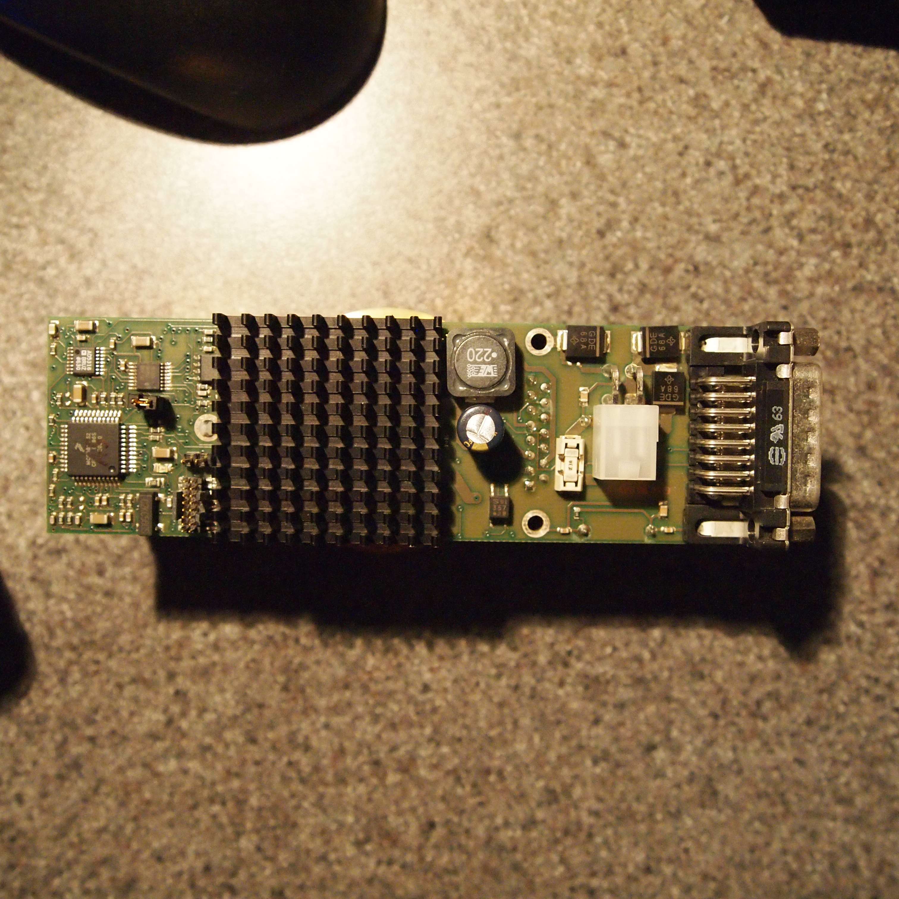
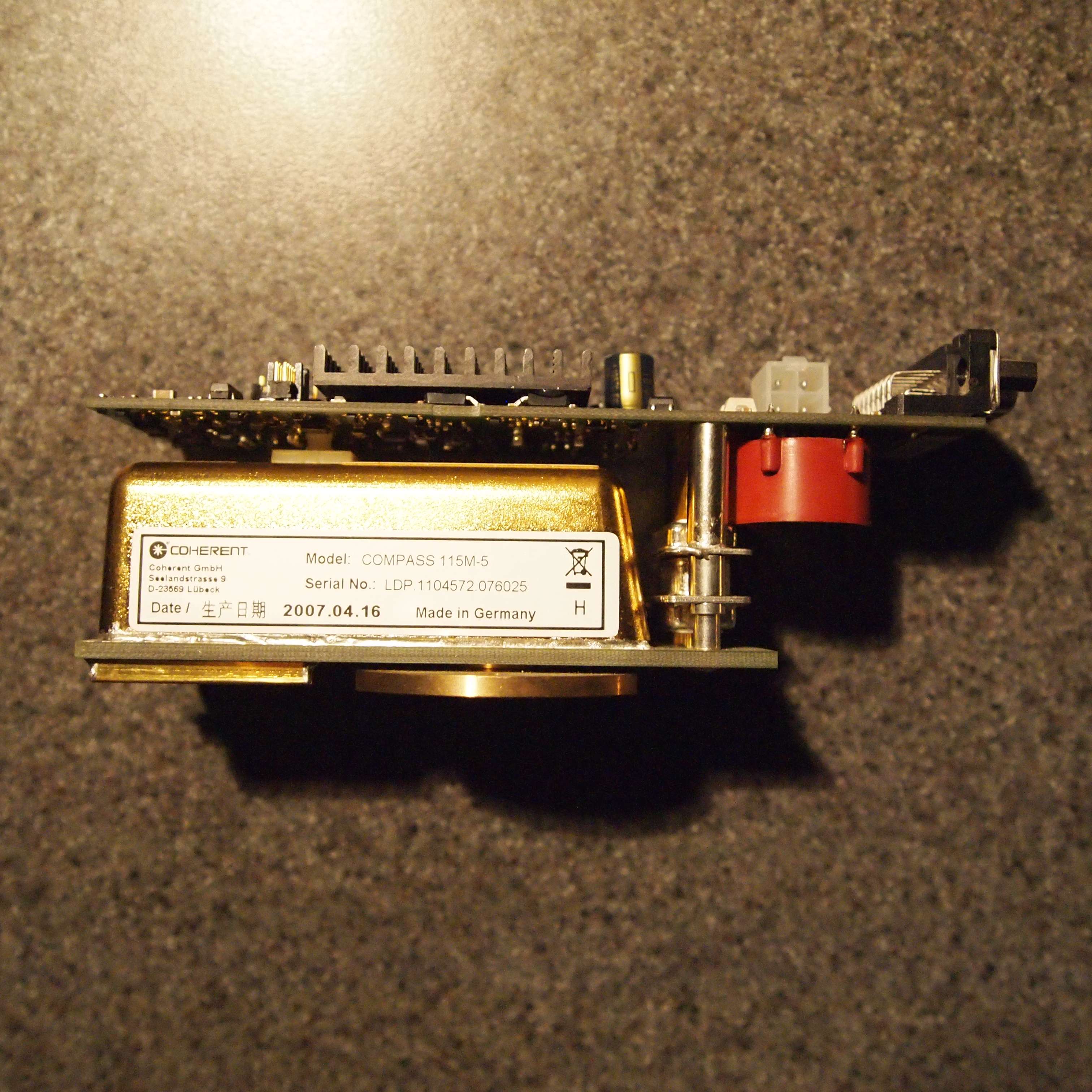
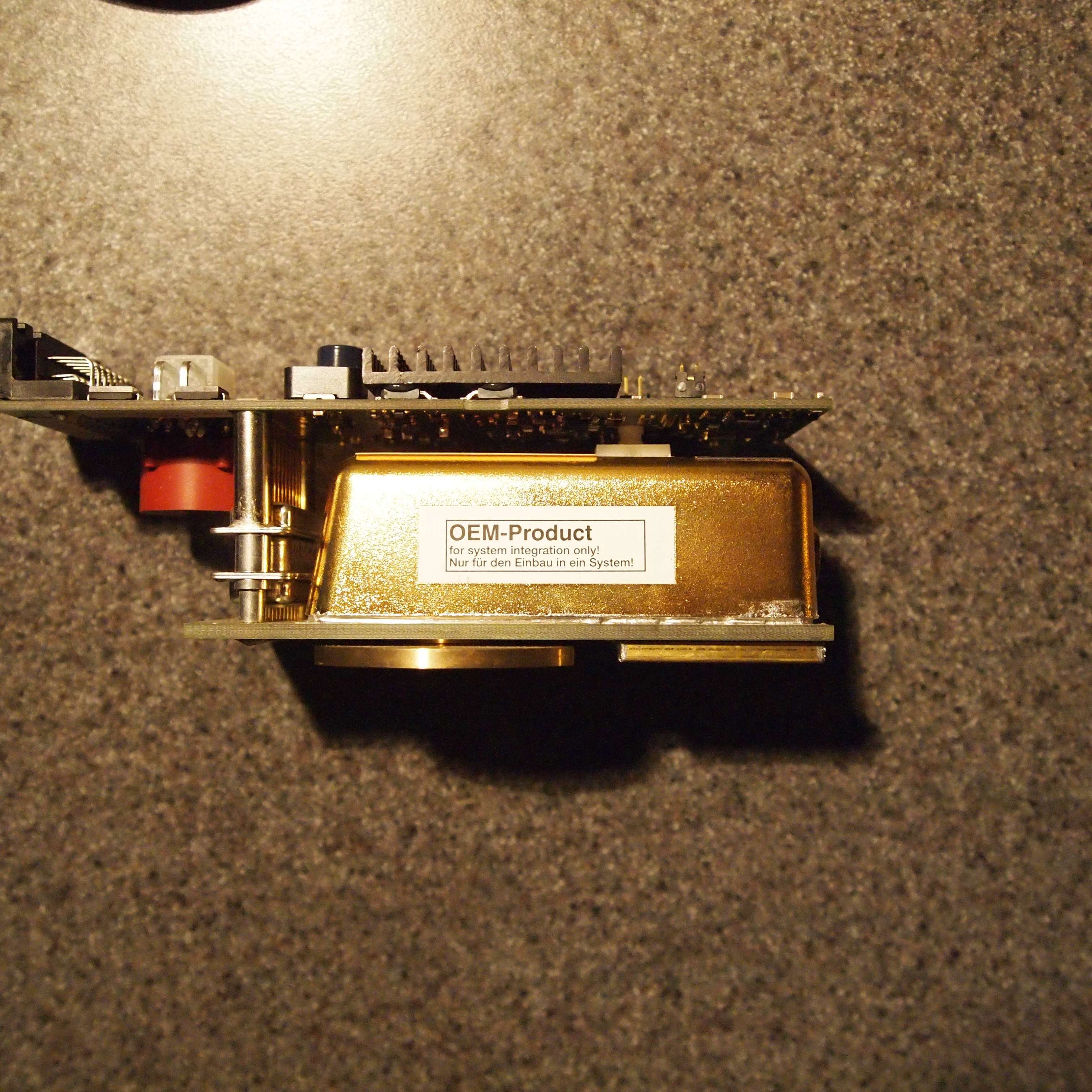
Howdy all I just pick up this Compass 115M-5 green laser module and need help finding the pin out for either of the sockets on it.

any help would be much appreciated, Thanks ;)


Joined
May 31, 2009
Messages
3,239
Points
63
Check out this link for more info....

Sam's Laser FAQ - Commercial Solid State Lasers

Analog Controller User Interface Signals
Here are the descriptions of the connections to the DB15M user interface. As noted, the C415M interface is similar or identical.

These are paraphrased from the C315M Operator's Manual:

Pin 1 - Interlock. The laser turns on only if this pin is connected to +5 VDC (for example, via a door switch). Opening the interlock loop turns the laser off immediately. After reconnection of the interlock loop, there is a three second delay before the laser is restarted. +5 VDC is available on pin 11. Current consumption of the interlock relay is approximately 100 mA.

Pin 2 - Laser On/Off (Command). The rising edge of this TTL signal turns the laser diode on and it must remain high while the laser is operating. The laser diode will be disabled if pin 6 (Power On/Off Status) is low.

Pin 3 - Power On/Off (Thermal Control, Command). The rising edge of this TTL signal turns on all thermal control loops (but not the laser diode). It must remain high during operation.

Pin 4 - Laser (Status). A TTL output (high=on) that can be used to monitor the status of the laser diode and hence the laser.

Pin 5 - Laser Diode Overcurrent (Status). A TTL output (high=fault) indicates a serious malfunction and should NEVER occur during normal operation. It is intended as a troubleshooting aid.

Pin 6 - Power On/Off (Status). A TTL output (high=on) that indicates the status of the Thermal Control components. The laser diode cannot be turned on if this signal is low.

Pin 7 - Overtemperature (Status). A TTL output (high=fault) indicates that the thermalized components probably including the LD, KTP, and RES, are too hot and the laser will shut down. It may be restarted once it has cooled down. (Power On/Off and Laser On/Off must be cycled to reset.) Unless there is a fault in the wiring or an internal short circuit, or a defective controller, it's not clear how this could happen unless the baseplate temperature were also marginal.

Pin 8 - Enter (Command). This TTL signal must be pulled down for at least 1 ms to transfer the setting of the power level pot to the internal memory and initiate a new power search cycle.

Pin 9 - Digital Ground. Pin 10 - Analog Ground. Analog and Digital Grounds are tied together inside the controller.

Pin 11 - +5 VDC Source. This output provides power to the digital controller and can be used for user circuitry attached to the 15 pin interface. The maximum current that can be taken safely from pin 11 is 200 mA. See the warnings above about this pin.

Pin 12 - Heat Sink Overtemperature (Status). This TTL output (high=fault) indicates that the case temperature is too high for the internal TECs to function properly. The laser will shut down and may be restarted once the laser has cooled down. A larger heatsink, more fans, or lower ambient temperature will be required.

Pin 13 - Laser Power Setpoint. This analog signal ranges from 0 to +5 V corresponding to a selected power from 0 to the maximum spec'd power for the laser. (Note that there is some conflicting information as to the range as elsewhere, it says it is from 50 to 100 percent of rated power.) This value must be entered into the controller's nonvolatile memory to become active.

Pin 14 - Power Monitor Output. Output voltage of 0 to 5 V indicates laser power from 0 to maximum spec'd value. For accurate power readings, it will be necessary to calibrate this signal with respect to calibrated reference.

Pin 15 - Laser Ready (Status). This TTL signal goes high when the actual output power is within a window of the selected output power. Thus, it may flash on momentarily during the search procedure while the laser is warming up. The laser can be assumed to have stabilized if this signal remains on for more than 30 seconds.
 
Last edited:
Joined
May 4, 2009
Messages
5,443
Points
113
Wow I just found that myself, thanks for the help though your a good man :beer:

Good old Sam's you can find almost any thing about lasers there.

now I guess I need to find a controller or build one my self, I did see there is a schematic for a simple one there.
 
Last edited:


Top