Another thing, that's why I am thinking of buying more than one type of laser (20mW, 100mW and 300mW maybe). So I can make all kinds of tests over here.
You'd be surprised how much 650nm is in ambient light. I used a PD and not a PT, but it should work similarly. I took a low tech approach to optical filtering; I mounted the PD inside a long (~2ft) tube with the end with the PD sealed off. This way only light very close to the axis could reach the PD. Even so, quiescent current was quite high outside of pitch black conditions (high as in tens to hundreds of uA). For my purpose it was acceptable since direct irradiation of the sensor by the laser beam was intended. But for your case where you're going to be reading a reflected highly diverged beam with lots of losses the signal level may not be significantly above the noise level. Just keep it in mind. Also remember that response time of the signal processing network comes in to play with such high frequencies. Fall times are also exceptionally important.
The shorter the distance you measure the greater the level of precision and accuracy needed to achieve comparable data acquisition.
yeah, I did something similar with optical filtering (a tube with the PT inside). In a quick test with a simple RC filter (to eliminate DC part of the PT signal) and a 532 DPSS laser flashing in a frequency of 10Hz I was able to sense its reflection in a chair that was about one meter away. I was not aware of the delay time of the DPSS lasers but I was focused in make the PT work. And it did with very simple circuitry with simple amplification. Now I will try to use a diode laser flashing faster and build something more sofisticated to read the reflection. I really dont need it to respond in exact 0.5ns but the shorter, the better.
I have all the modules (cases) of those green DPSS lasers that I've tested here. It seems like the diode laser and all other stuff needed by the DPSS are all glued inside. Is it possible to disassemble it and use its copper module to work with my 20mW red diode lasers? Or I really need to buy those modules with them?
oh, I also bought a camera lens filter which is green to use as optical filter. But I started to think that maybe it reflects and absorb more than what it helps filtering. Also I was trying to use a camera lens inside the tube which was going to focus all the light in the PT (I used more than one). But maybe this was a bad idea also because the amount of lens that are inside it, maybe absorb a lot of light... and this may be worse than without lens.
Anyway, the best results were with a simple PT receiving light directly and its position is right after the laser diode. They are next to each other pointing to the same wall in a paralell way. And again, the ambient light were not a problem due to the flashing frequency that is very helpful because its only a matter of filtering the PT signal and removing all other frequencies. So I dont think the ambient light is really a great problem. Dont you agree?
The faster the pulse the more ambient light conditions will interfere. As always the higher the frequency the more a good S/N ratio matters.
As for the dpss modules, it is not possible to use them for the red diodes. They tend to epoxy the pump diode (which may not even be 5.6mm!) into the press-fit diode housing part of the module. I tried removing one once and it was a farce.
But why greater the frequency, more the ambient light affects me? If I will filter my frequency of interest (let's say 1MHz) with a nice band-pass filter, would not only beams flashing in that frequency disturb my system?
Because the linearity between optical occurrences and electrical occurrences is not unity. In other words electrical filtering cannot completely make up for optical errors. Too much optical noise can saturate the detector so that there is not enough differential between the output signal when there is laser light and when there is no laser light. Sunlight is often the cause of this in real world applications.
If you're getting a 120Hz saturation on your detector from ambient light (fluorescent lighting for example) then you're not going to see the 1MHz signal at all during the 4.2mS high periods from the ambient noise. At best electrical filtering will cause the unit to see no signal at all and report a LO instead of a 4.2mS long HI. Understand?
So the main problem is saturation, aint that right?
If so, again I think it can be compensated. Take a look:
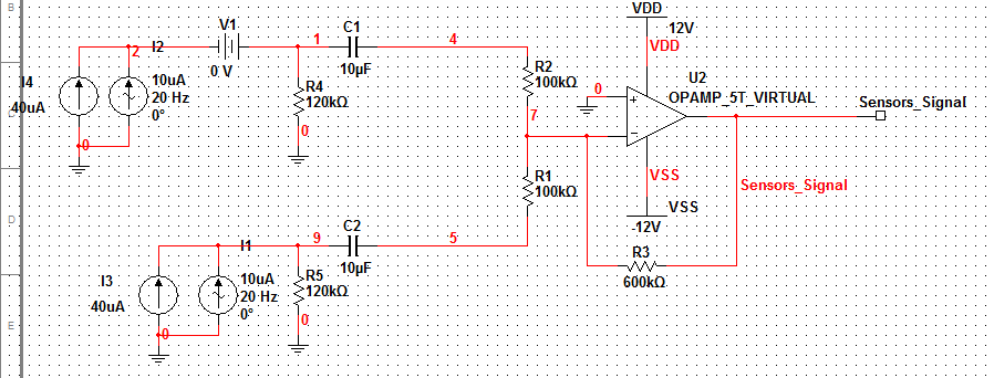
This is basic idea behind my PT signals. I put them as simple current sources (just for simulation purposes). I also put 2 current sources (one is DC and the other is AC) so I could simulate a DC level (ambient light) plus AC noise (including laser signal).
So, that R4 and C1 act like a filter which eliminates the DC level.
There are two identical circuitry just to simulate the use of one or more PT and adding them. That's why is important to remove DC part of the signal so it does not saturate soon. Then the Op-amp will add them and amplify the resultant signal.
My point is: R4 (and also R5 if using more than one PT) can be ajusted so the signal does not saturate, can't they? I can also use a digital potentiometer so a microcontroller can ajust the resistance as the signal is saturating. This way, there is always gonna be a signal passing through capacitor C1 that can be amplified and filtered around my frequency of interest. The op-amp gain also could be ajustable.
Am I missing anything? Do you think this still can give me problems with high frequency + ambient light?
That will prevent electrical saturation but not optical saturation. I used a similar scheme for my AM laser transceiver which used a 650nm centered photodiode as a receiver, and I noticed that the gain was reduced as ambient light level increased, because even though electrical side saturation was prevented, the quiescent operating point of the PD coincided with the ambient light level. Thus the peak-to-peak profile of the signal after the high-pass/DC-blocking section was inversely proportional to the ambient light level. Being simple audio production it was not a major issue, but if the P-P profile gets reduced below threshold levels for your signal detection/timing circuit you'll need greater amplification to restore functionality. You might be able to put in some kind of automatic gain control, but I have no knowledge of such implementation methods.
What exactly is and is not acceptable in terms of S/N ratio will be largely based on what you're using to detect the presence of a bounce signal. Unfortunately I don't have any experience with such circuits (I tend to work with simple TTL voltage controlled stuff when it comes to pulse trains and switching) so I can't really advise on it.
Try assuming a maximum range of current for your PT current source simulation and then varying the noise sources intensity to occupy an increasingly larger portion of the maximum range. This will more closely approximate optical saturation.
Example: if the PT can source a maximum of 100uA, try having the DC source at 50uA for moderate ambient light, and then the AC source at 20uA. Now add in a 1MHz DC Pulse source (or AC if you can't do DC pulse) that is the data from your PT and set it to be the remaining 30uA. Observe the outputs. Repeat while varying the currents of the three sources (DC-ambient, AC-noise, DC/AC-signal) while remembering to make sure all the currents add up to an assumed maximum current output from a real-world PT.
I'm not sure I follow you, but I think I do. You mean that even if I adjust the electrical gain of the PT to not reaching its maximum current, the problem will still exists because the larger the ambient light, lower will be the pulses in a relative way. I mean, as soon as the ambient light increases I will reduce the PT gain to maintain the desired output current. Doing that I will reduce the laser pulses gain and they will be lower after DC-blocking filter. is that right?
I've never thought of that before, thanks! Anyway, my idea was to "hide" the PT inside a little tube as we talked before. And hold that tube in a horizontal way so the sunlight and most ambient lights will not affect it directly. What other things I could do to prevent this problem? Optical filters? Maybe with IR instead of 650nm I could have more alternatives?
The off axis blocking tube does help greatly but it also reduces reflected signal pickup because reflected beams lose phase cohesion and lose coherence.
A narrow band pass optical filter is the generally accepted method (it is what they do for IR) but those filters can be expensive.
I would not recommend using IR as the beam specs are worse, alignment is worlds harder, and there is more IR in most natural light than there is 650nm.
Excuse the noobie question.
But doesn't the very notion of DPSS means that a SSD diode will be used as the name suggest... Diode Pumped Solid State laser...
Cos... well most of the solid state lasers we see this days are optically pumped with a laser diode anyway...
OPSL, DPSS, etc lasers are not good for pulsed data operations due to delays and non-linearity of the non-linear crystals which do the wavelength changing magics.
In a bare diode laser the only delay is from the junction capacitance. The delays from the crystals are orders of magnitude greater than the one from the junction.
Most DPSS units can't handle modulation over 100KHz or so (special lab systems are a different story), where as your dollar store 658nm diode can easily do 800KHz without any issue.
only by looking at a laser diode housing/host how can I know the maximum safety power of the laser diode to use with it and also know if I would need a press-tool or not to mount the diode inside it?
The way most of us determine if a heatsink is sufficient for a certain power level is simply judging by experience. Unfortunately that does not really help you much. There is a lot of math that can be used for the task, but I don't know any of it. I've worked with electronics enough to be able to determine if a heatsink is sufficient simply by knowing the power the device is expected to dissipate.
As for knowing whether you need a press fit tool or not, it is a matter of inspecting the hardware. If it is a bare diode and a press-fit mount (you have to know what they look like) then you need a press tool. If it is not a press fit mount, you don't need a press tool.