Welcome to Laser Pointer Forums - discuss green laser pointers, blue laser pointers, and all types of lasers

LPF Donation via Stripe | LPF Donation - Other Methods

Links below open in new window

ArcticMyst Security by Avery

Uniphase 2114P-40MLA & 2214-40MLA Argon Ion Laser

Joined
Dec 11, 2011
Messages
4,364
Points
83
Hello photon fanatics!

I recently purchased a very nice cyllindrical argon ion laser head and matching psu from Daguin during one of his massive clean outs. I've been wanting one of these lasers since I was a kid and first saw a single line 488 that I think did a whopping 10mW at some insane power input level. Finally I have a beautiful one of my own, and it is a killer 80mW max multiline as well! I have been able to get SEVEN lines out of this amazing machine.

The unit did not come with a remote, but Dave included a DB25 headder jumpered to idle. Links to a schematic for a remote on RepairFAQ.org were posted for me and I ordered parts and drew up a schematic. I finally test the remote design and it did not work! I first contacted Dave, then later Sam at RepairFAQ, but no one knew why exactly. I did some probing, experimenting, and digging around and discovered that the pins listed as "ground" pins were not actually ground pins at all! Some were negative voltage rails as low as -30V!

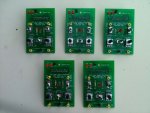
So, I found a scanned version of the manual for this series power supply which lo and behold stated that only Pin 11 was to be used for the return paths (i.e. ground) for the various functions. A not so quickly installed mass of jumpers on Dave's headder and it worked! Okay, time to redraw the schematic and get building. I spent about three and a half hours building the remote, but I did not want to take any short cuts and chance another failure or error.

I'm still having issues with "Discharge Enable" and the Interlock system not turning off power to the laser tube when they are supposed to. It appears that Discharge being put to disable while the laser is in Run mode and above a certain current threshold will actually turn off the laser tube current, but I haven't tested it much. I wrote Sam another email informing him of progress, he might have some more info as well. I am trying to avoid opening the power supply at all costs.

Here are the results:

argonioncurrentremote.png


remoteinfo.jpg


remoteqi.jpg


remote1.jpg


multiline1.jpg


multiline2.jpg


More Pics and Videos to come!
 
Last edited:


daguin

0
Joined
Mar 29, 2008
Messages
15,989
Points
113
Thank you for your work with this
JDSU must have changed something in the PSU's
JDSU would do "customizations" for big clients
Or maybe it is just that PSU :undecided:

I think have a "keyless" version of this switchable "gold" model PSU here
The remote turns the tube current on and off just as expected

Maybe we should look for any "sub-model" designation and/or the date of manufacture to see if your model was "customized" for some particular application

Peace,
dave
 

daguin

0
Joined
Mar 29, 2008
Messages
15,989
Points
113
This is the info from the PSU I have on hand


I wonder if anyone else on the forum has run into this challenge?

nice.... any chance you'd build me one, as I don't have the time ?

You could have a small cottage industry making these ;)

Peace,
dave
 
Last edited:
Joined
Feb 1, 2008
Messages
2,894
Points
0
I had a gold 20SL model PSU, and then info on Sam's site was partially helpful.

My "enables" all worked, but none of the mode switching or current/light monitoring pins appeared to work.
 
Joined
Sep 22, 2010
Messages
1,358
Points
48
Welcome to the club! Multiline argons are amazing beats to behold in person. They also make one helluva space heater in the winter too. :eg: That awesome yours does seven lines. The one I have only does six but I swear it did seven off the original PSU before it blew up. Great pics too. They make me want to get off my duff and get around to doing a few things so I can finally finish the write up I started ages ago.
 
Joined
Dec 11, 2011
Messages
4,364
Points
83
More Pics and an 8th line!

Last night I was running the tube at 7A for quite some time and I was playing around with a prism and my 1000line diffraction grating. I managed to spread the beam out wide enough with the grating to get a good clear shot of the beams, but had to put my room lights on to make the camera happy, and to my surprise an 8th line popped up!

8lines.jpg


multiline3.jpg


All of the possible Ar Ion wavelengths are: 351.1 nm, 363.8 nm, 454.6 nm, 457.9 nm, 465.8 nm, 472.6nm, 476.5 nm, 488.0 nm, 496.5 nm, 501.7 nm, 514.5 nm, 528.7 nm, and 1092.3 nm.

The above picture shows: 457.9 nm, 465.8 nm, 472.6nm, 476.5 nm, 488.0 nm, 496.5 nm, 501.7 nm, 514.5 nm.

One thing I would really love to have one day is a single line 351.1nm Argon laser, even if it is only 10mW.

Thank you for your work with this
JDSU must have changed something in the PSU's
JDSU would do "customizations" for big clients
Or maybe it is just that PSU :undecided:

I think have a "keyless" version of this switchable "gold" model PSU here
The remote turns the tube current on and off just as expected

Maybe we should look for any "sub-model" designation and/or the date of manufacture to see if your model was "customized" for some particular application

Peace,
dave

This PSU was made several years before the one you posted a picture of. At least from observing this unit it seems the interlock was poorly designed, it wouldn't surprise me if they redesigned it after they changed to JDSU from Uniphase.

nice.... any chance you'd build me one, as I don't have the time ?

I might be up for such a project in the near future. I have a full plate right now though but I'll let you know how it goes. I'll have to work out a price (both for parts and for labor) too. I know I sprung for a nice 10T potentiometer which was $12. Such lavish expenses could certainly be toned down for production. Likewise I could skip all the wire extensions and cut several hours of labor out of it. I wanted to allow for complete dissassembly in case of errors or malfunctions, so I did not solder any components to the wire leads themselves, hence the seven terminal blocks! I would need to know the maximum safe current for your tube/head and the range of current you want the remote to select.

Off the top of my head:
Box $6
Pot $4
Switches $3
Cable: $8
Board/Solder/Wire/Hardware: $10

So that is about $30 in parts. Not sure what labor would come to, I'd have to figure everything else out first.

I had a gold 20SL model PSU, and then info on Sam's site was partially helpful.

My "enables" all worked, but none of the mode switching or current/light monitoring pins appeared to work.

What pins did you use for return paths for the mode switching or monitoring?


@Daguin, what kind of diffraction grating did you use and where did you get it? I think you said it was a mirror optic - that would be ideal as transmission gratings split the beam up many times reducing individual beam power by a lot. A reflective split would preserve a lot of the beam power. The prism I have is good for this but it barely spreads the wavelengths at all. After about 15ft the dots are still touching each other.
 
Last edited:

daguin

0
Joined
Mar 29, 2008
Messages
15,989
Points
113
This PSU was made several years before the one you posted a picture of. At least from observing this unit it seems the interlock was poorly designed, it wouldn't surprise me if they redesigned it after they changed to JDSU from Uniphase.

So maybe I should keep the other schematic on hand as well?


I might be up for such a project in the near future. I have a full plate right now though but I'll let you know how it goes. I'll have to work out a price (both for parts and for labor) too. I know I sprung for a nice 10T potentiometer which was $12. Such lavish expenses could certainly be toned down for production. Likewise I could skip all the wire extensions and cut several hours of labor out of it. I wanted to allow for complete dissassembly in case of errors or malfunctions, so I did not solder any components to the wire leads themselves, hence the seven terminal blocks! I would need to know the maximum safe current for your tube/head and the range of current you want the remote to select.

Off the top of my head:
Box $6
Pot $4
Switches $3
Cable: $8
Board/Solder/Wire/Hardware: $10

So that is about $30 in parts. Not sure what labor would come to, I'd have to figure everything else out first.

IIRC another member talked about building these, but didn't follow through
He had several inquiries at the time


@Daguin, what kind of diffraction grating did you use and where did you get it? I think you said it was a mirror optic - that would be ideal as transmission gratings split the beam up many times reducing individual beam power by a lot. A reflective split would preserve a lot of the beam power. The prism I have is good for this but it barely spreads the wavelengths at all. After about 15ft the dots are still touching each other.

I ran through a lot of diffraction mirrors off of eBay a few years ago.
Most had some kind of damage are were of poor quality
The one I use now is housed in an assembly that has a "door" to protect the mirror
It is a "780nm Full Spectrum" grating
Unless you are willing to spend the big bucks that are charged for new, you just have to keep your eyes open and take a chance on them

Peace,
dave
 
Joined
Dec 11, 2011
Messages
4,364
Points
83
I found this by searching but I don't know what it means by design wavelength, a diffraction grating's wavelength range is determined by how many lines per mm, so I'm thinking these numbers are based on a certain wavelength being reflected at a certain angle.

1200 Grooves, 1000nm Ruled Diffraction Grating, 12.7mm Square | Edmund Optics

The price isn't bad but isn't great either. I'll keep watching ebay.


I wouldn't mind making remotes for sale as long as I can do it without being at a loss. The hardest part is allocating the time and ochestrating the logistics of such an undertaking. I've already done most of the work as far as pinouts and research goes.

Ditch the old schematic. After I found the manual I learned that there really isn't 20mA available from pin 13... lots of other things use 3mA or so each. You're left with I think 10.4mA to work with, so the design with a switch to switch between 7A and variable won't work - it'l overload the 15V rail. The new schematic should work for all models. Pin 11 is a designated return for the +15V rail on every model, the manual just says that the other pins work for various models as well (but not mine).
 
Joined
Sep 12, 2007
Messages
9,399
Points
113
You forgot 472.6nm. If you look at the relative gains of each line, you'll see you don't have 454.6, you have 472.6.

There are a few other features you could add to your remote. Light mode, light mode adjust, and output power readout for example. It is recommended you operate your laser in light mode if possible, by the way.
 
Joined
Dec 11, 2011
Messages
4,364
Points
83
You forgot 472.6nm. If you look at the relative gains of each line, you'll see you don't have 454.6, you have 472.6.

There are a few other features you could add to your remote. Light mode, light mode adjust, and output power readout for example. It is recommended you operate your laser in light mode if possible, by the way.

Ooh, thanks for the correction. I pulled up wiki for the wavelength series but it omitted that line. I delved deeper and it seems you are right, though the chart I found says both 454.6 and 472.6 have the same relative gains, but based on wavelength spacing judging from my pics it is indeed 472.6. http://www.plasmalabs.com/production/Ion_lasers

I'm curious about the light mode recommendation; there would be no means to limit the tube current to safe levels, and RepairFAQ states that light mode only goes up to 60mW (though the PSU manual says it will go up to 150mW). Either way it would complicate things a bit to implement. The manual states that current control mode is usually used for repairs and checking the life of the tube, but it doesn't say it shouldn't be run there. Is there any more info to the light mode recommendation?


P.S. I wonder what the minimum output power needed would be to SHG the output with some BBO...
 
Last edited:
Joined
Sep 12, 2007
Messages
9,399
Points
113
the chart I found says both 454.6 and 472.6 have the same relative gains

Well you can always pick out 458, 488, and 515 because they're the brightest (in their respective colors anyway). Since you don't have a dim line on the other side of 458, that means there is no 455nm present.

I'm curious about the light mode recommendation; there would be no means to limit the tube current to safe levels, and RepairFAQ states that light mode only goes up to 60mW

It will still limit the current to some upper limit even if you removed the pickoff, for example. The PSU is not going to blow itself up if the pickoff system fails or becomes misaligned, that would be a major design flaw. I'm not sure about the light mode upper limit. My small SL unit (spectra physics 163) that has the same interface only goes up to 50mW at 10A, so it doesn't apply to me. Like I said, if possible. You shouldn't be running these higher than 8A for too long anyway.

it would complicate things a bit to implement.

Not at all. There's a crude diagram on the FAQ that I followed and works fine. DPDT switch is all you need. Switch the light/current mode on one pole, and switch the pot output to light or current set-point with the other pole.

Is there any more info to the light mode recommendation?

The plasma can oscillate, even if you have the current well regulated. Light-mode detects and stabilizes these oscillations. There's a paragraph or two on the FAQ.
 
Joined
Dec 11, 2011
Messages
4,364
Points
83
It will still limit the current to some upper limit even if you removed the pickoff, for example. The PSU is not going to blow itself up if the pickoff system fails or becomes misaligned, that would be a major design flaw. I'm not sure about the light mode upper limit. My small SL unit (spectra physics 163) that has the same interface only goes up to 50mW at 10A, so it doesn't apply to me. Like I said, if possible. You shouldn't be running these higher than 8A for too long anyway.


Not at all. There's a crude diagram on the FAQ that I followed and works fine. DPDT switch is all you need. Switch the light/current mode on one pole, and switch the pot output to light or current set-point with the other pole.


The plasma can oscillate, even if you have the current well regulated. Light-mode detects and stabilizes these oscillations. There's a paragraph or two on the FAQ.

Right, this PSU goes up to 12A, but the tube should not be run over 10.5A at all, and running above 9.5A can cause filament wear and failure. What I was getting at is that for light mode operation I would need to find where the 9.5A safe limit is on the light mode operational range. I'd also have to make another limiting divider like I did for the current side but for the light side - you can't use the same one since the light scale and current scale do not coincide as far as applied voltage. The voltage needed for 7A (40mW) on pin 6 (current) is not the same as the voltage needed for 40mW on pin 7 (light). Due to how little current is available from Pin 13 for the control circuitry (a mere 10.5mA) you can't have both dividers constantly hooked up to Pin 13 without using much higher value divider resistors (so I would need to replace the one I'm using, or install another switch that disconnects the divider not currently in use). The schematic on FAQ is meant for ease of construction, not precise control with firm safety features. In the remote section of the manual it states how the lower end models of remotes should be calibrated to the particular head to limit current to safe levels via trimpots on the PCB.

Interesting about the plasma oscillations. I think this is more of an issue that could cause problems for applications of the laser and not the laser it self. The manual states that "the idle function is used whenever possible to prolong laser tube life" and that "while in idle the laser operates in current control mode at aproximately 4 amps". It later mentions optical noise will be present due to temperature based fluctuations in current mode. It seems strange that a mode which prolongs life could potentially damage the laser. I'm not disagreeing that light mode may be generally recommended, I'm just of the opinion that it will cause the unit no harm to be in current mode as long as the current level is below the maximum safe limit.
 
Last edited:
Joined
Sep 12, 2007
Messages
9,399
Points
113
you can't use the same one since the light scale and current scale do not coincide as far as applied voltage.

They're pretty close for me. What's wrong with adjusting the pot? You're gonna have to do it anyway.

Due to how little current is available from Pin 13 for the control circuitry (a mere 10.5mA) you can't have both dividers constantly hooked up to Pin 13 without using much higher value divider resistors (so I would need to replace the one I'm using, or install another switch that disconnects the divider not currently in use).

Or just leave both outputs connected to the set pins, and switch power to each divider instead. You still only need a DPDT. Come to think of it, you could use the same divider, and switch in/out an additional divider resistor to more closely match the input levels for each mode if that's what you're worried about. You're giving up too easily.

I think this is more of an issue that could cause problems for applications of the laser and not the laser it self.

Incorrect. Read the entry on the FAQ.
 
Last edited:
Joined
Dec 11, 2011
Messages
4,364
Points
83
They're pretty close for me. What's wrong with adjusting the pot? You're gonna have to do it anyway.

It is off by almost a factor of two for my unit. 0-4.5V for current vs. 0-8V for light.


cyparagon said:
Incorrect. Read the entry on the FAQ.

I finally just found this blurb/section. Now I am curious; it says several air cooled PSUs engage the light feedback loop to prevent oscillations even when set to current control mode. I'm going to email Sam and see if he knows if this model does this. I'll see if I can set up the photodiode test he recommends to check for oscillations.

Btw, even RepairFAQ misses the 472nm line at one point:

Argon ion visible lines (8 UV lines and 2 IR lines ignored):
454.6 nm, 457.9 nm, 465.8 nm, 476.5 nm, 488.0 nm, 496.5 nm, 501.7 nm, 514.5 nm, 528.7 nm.


UPDATE: I scoped the light output of the laser using my AM laser receiver and found some high frequency oscillations on the light output only when the laser was set to idle or set below about 5 amps of current]. Above this level I saw only 25mVpk ripple on a 9V bias, so that is 0.27% (0.002722) Vripple or 99.7% regulation. I'm going to rig up a quick light conrol remote with the spare DB25 connector and scope the laser's own light monitor and see how it compares.
 
Last edited:
Joined
Dec 31, 2012
Messages
904
Points
0
You could have a small cottage industry making these ;)

The supply is there, the demand is not. I still have five left from my last batch of PSU controllers for the JDSU 2110 PSU.

The style shown in the pictures is without displays or enclosure to keep costs down. One must use their DMM for the output display.
 

Attachments

  • Argon-Laser-PSU-Controllor-Batch2.jpg
    Argon-Laser-PSU-Controllor-Batch2.jpg
    27.2 KB · Views: 235


Top