Welcome to Laser Pointer Forums - discuss green laser pointers, blue laser pointers, and all types of lasers

LPF Donation via Stripe | LPF Donation - Other Methods

Links below open in new window

ArcticMyst Security by Avery

PCB stencils

Joined
Aug 30, 2008
Messages
6,891
Points
83
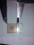
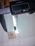
I was talking to Laen over at OSH Park and he and a friend have been working on using a 40W CO2 laser to cut PCB stencils. However, every time they try, their stencil ends up getting warped.
They are cutting kapton.

Would anyone know why this is happening (obviously from the heat) but why it's happening to them while others can make stencils fine.


Joined
Feb 10, 2012
Messages
330
Points
0
Hi Moh,

Could be spot size / cutting speed combination....how does the speed you cut at compared to the system that works.
Smaller spot and a fast speed will limit the heat build up. A high power density will ensure the cut is vapourised instead of 'melted'
Also could be optics causing splash that is heating up the surrounding area of the cut???
ATB
MM
 

LSRFAQ

0
Joined
May 8, 2009
Messages
1,155
Points
83
My educated guess would Spot size, focus, splash, and lack of assist gas.

They may also need a vacuum platen instead of the mesh.

Steve
 
Last edited:
Joined
Jun 1, 2013
Messages
3
Points
3
I was making stencils with CO2 the last week but I keep looking how to make an even small spot on paper and plastic.
Actually I get 0.2mm, but depends too much on the focus/table height, the air flow to cool down the plastics sheets, the source power, speed.
I think 0.2 can be improved. Does anyone got below that ? 0.1, 0.0xx ?

If you make in plastic, can be reused many times, retain the proportions and you can fix it much better to the PCB because "is transparent" :)

Spots:
bayimg - image: 2013-06-01-191831_1920x1080_scro - free uncensored image hosting
bayimg - image: IMG_20130601_191153.jpg - free uncensored image hosting

BGA: bayimg - image: 2013-06-01-192107_1920x1080_scro - free uncensored image hosting
Fine flying lines: bayimg - image: 2013-06-01-192313_1920x1080_scro - free uncensored image hosting

Optimizing toke a while:
bayimg - image: IMG_20130601_192117.jpg - free uncensored image hosting

<b>My questions:</b>
Will a "CVD ZnSe Focal Lens" with different focus length improve the spot size ?
Which focal lens are recommended to avoid reflections ?
 
Joined
Sep 12, 2007
Messages
9,399
Points
113
A shorter focal length will result in a smaller spot size. The disadvantage is they're more difficult to manufacture and require more material (more cost), and they likelihood of lens damage increases because the lens is closer to the flame/splatter. Air assist will usually prevent that, though.

Any lens with an AR coating will help avoid reflections by definition, and most ZnSe lenses will have this coating anyway.
 
Last edited:

Spooky

0
Joined
Jun 1, 2013
Messages
261
Points
0
Useful depth of field is calculated by the following

D = Diameter of input laser beam from tube.
F = Focal length of the lens we are using.
W = Wavelength of the laser tubes beam.
DOF = Useful depth of field for a given optical set up.

The equation goes as follows:

DOF = 2.5 x W x (F/D) squared.

The industrial standard for useful DOF is 1.4x the focussed beam diameter in each direction.

a 25mm (1 inch) focal lens will give great power density and tiny spot size but an almost insignificant DOF.

In practical application Lasers cannot have a spot smaller than their wavelength however there have been experiments at MIT and Cambridge that have achieved smaller than Wave spot sizes.

Kapton (poly(4,4'-oxydiphenylene-pyromellitimide)) has a very wide thermal stability band, without a good air assist it's likely to warp as you rightly say.

I don't really like cutting Kapton but with 40PSI of air assist it's nt too bad.

For stencils Mylar could be a better option,

best wishes

Dave
 
Joined
Jun 1, 2013
Messages
3
Points
3
I'm in continuous progress, each day I improve the stencil even better.
These photos are more than a week old and was my first try, Take a look how easy to apply is with transparent stencil vs metal sheets stencil.

I found 2 interesting things:
1) Transparent is better to align.
2) Flexible is easier to make multiple PCB
3) If something went wrong, I can clean the wrong area, put the stencil even with some components already plugged, and re-apply the solder paste.
4) Cost !
5) Manufacturing Speed !

For example, If I had already plugged the first IC (starting from the stencil), and later something go wrong in the second (shaking hand when plugin the IC, etc..), I can clean the affected area, reapply the stencil over the secondIC, even if the firstone or any other low-profile component is already in the PCB.

"That with metal is impossible, you will have to clean all the PCB and reapply all components from the start !"

Take a look:
bayimg - image: 956.jpg - free uncensored image hosting
bayimg - image: 957.jpg - free uncensored image hosting
bayimg - image: 959.jpg - free uncensored image hosting
bayimg - image: 960.jpg - free uncensored image hosting
bayimg - image: 961.jpg - free uncensored image hosting
bayimg - image: 964.jpg - free uncensored image hosting
bayimg - image: 967.jpg - free uncensored image hosting
bayimg - image: 969.jpg - free uncensored image hosting

The smallest IC is an MLF32
 
Last edited:
Joined
Jun 1, 2013
Messages
3
Points
3
Hi,

I was updating optics in the last days and here are some new achievements.
A BGA of AllWinner A80, 0,65mm dot pitch.

BTW, this is only a test, since the only materia I have is 0,48 thick. Too thick to use solder paste. Should be 0.1mm approximately.
 

Attachments

  • Stencil_HQ_01.resized.jpg
    Stencil_HQ_01.resized.jpg
    81 KB · Views: 140
  • Stencil_HQ_02.resized.jpg
    Stencil_HQ_02.resized.jpg
    90 KB · Views: 86
  • Stencil_HQ_03.resized.jpg
    Stencil_HQ_03.resized.jpg
    140.9 KB · Views: 115


Top