- Joined
- Oct 21, 2015
- Messages
- 12
- Points
- 3
This is my first post, so hi everybody ")
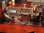
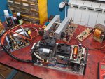
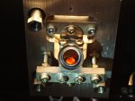
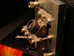
I recently saved a NEC GLS-3030 (actually it is marked 3032) head from a gruesome fate, without the PSU. Never thought it would be of any use but after inspecting the tube I think there may be a chance to bring it back to life. Brief condition of the tube/head:
- no mechanical damage
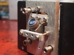
- one mirror misaligned, somebody has played with the screws/mounting
- hours count: 00351 (makes no sense, I think it has way more)
- getters worn out, but some central areas still hold out (metallic patch)
- filament has sagged visibly in the middle (1-1.5mm), but still operational without any shorts, rough guess (hope that is still does not obstruct the bore
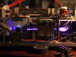
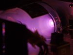
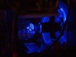
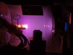
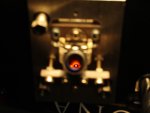
- when hooked to HeNe power supply the tube glows light-purple (like it should, I guess)
I set up a precisely regulated filament power supply (2.7V-3.3V) which works nicely, so next should be the main anode power. My questions are:
1. Is it safe to look unprotected at this tube while it works? (from the side of course Does the plasma discharge emit anything dangerous to the eyes? If I get to the point of mirror alignment, there's gonna be a lot of fiddling/staring around the working tube. I was unable to find any guidelines regarding this issue anywhere.
2. I do not have the cover for this laser head, can I run it for prolonged periods with the fan blowing only at the heatsink?
3. If I get it to start, any advice on the mirror alignment? I have a HeNe head to start with...
Thanks in advance!
I recently saved a NEC GLS-3030 (actually it is marked 3032) head from a gruesome fate, without the PSU. Never thought it would be of any use but after inspecting the tube I think there may be a chance to bring it back to life. Brief condition of the tube/head:
- no mechanical damage
- one mirror misaligned, somebody has played with the screws/mounting
- hours count: 00351 (makes no sense, I think it has way more)
- getters worn out, but some central areas still hold out (metallic patch)
- filament has sagged visibly in the middle (1-1.5mm), but still operational without any shorts, rough guess (hope
that is still does not obstruct the bore- when hooked to HeNe power supply the tube glows light-purple (like it should, I guess)
I set up a precisely regulated filament power supply (2.7V-3.3V) which works nicely, so next should be the main anode power. My questions are:
1. Is it safe to look unprotected at this tube while it works? (from the side of course
Does the plasma discharge emit anything dangerous to the eyes? If I get to the point of mirror alignment, there's gonna be a lot of fiddling/staring around the working tube. I was unable to find any guidelines regarding this issue anywhere.2. I do not have the cover for this laser head, can I run it for prolonged periods with the fan blowing only at the heatsink?
3. If I get it to start, any advice on the mirror alignment? I have a HeNe head to start with...
Thanks in advance!