Welcome to Laser Pointer Forums - discuss green laser pointers, blue laser pointers, and all types of lasers

LPF Donation via Stripe | LPF Donation - Other Methods

Links below open in new window

ArcticMyst Security by Avery

Using a DC/DC converter to power the laser

woop

0
Joined
Nov 9, 2007
Messages
342
Points
0
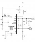
yeah its that complicated cos its a schematic for a demo board. you could cut away most of the stuff at the bottom.

phenol-
the higher the reference voltage, the more power will have to be wasted in the shunt to measure the current. so if you have a 1.25v ref, you will be wasting 30% of the total power in the shunt if you are running a 3V diode. that being said, if you don't care about efficiency and you are using a boost configuration, it doesn't matter.

btw with a .235V ref as with the ncp3065, only 7% of total power is wasted in the shunt when running a 3V diode.
and also, the 3065 is avaliable in your normal through-hole package


phenol

0
Joined
Oct 30, 2007
Messages
533
Points
18
woop said:
phenol-
the higher the reference voltage, the more power will have to be wasted in the shunt to measure the current. so if you have a 1.25v ref, you will be wasting 30% of the total power in the shunt if you are running a 3V diode. that being said, if you don't care about efficiency and you are using a boost configuration, it doesn't matter.

btw with a .235V ref as with the ncp3065, only 7% of total power is wasted in the shunt when running a 3V diode.
and also, the 3065 is avaliable in your normal through-hole package
i will use a low value sense resistor and a summing op amp to get the potential difference across it multiplied by, for instance, 10. then, for Vref=1.25V and gain of 10, the drop across the shunt will only be 125mV. this does get things complicated, though, and puts stability in question.
 

IgorT

0
Joined
Oct 24, 2007
Messages
4,177
Points
0
After testing the MAX756 circuit for a couple of days now, i realized it's not so great after all..

I'm still waiting for the correct coils, but i did wind several of my own, that should be good, according to my calculations, and even tried a bit more and a bit less just to make sure.. I hope my coils or calculations were bad, or the right (and expensive) ones won't help much at all.. :(


This circuit is supposed to be capable of producing 200mA @ 5V, down to 2V of input voltage, or 300mA @ 3.3V, down to 1.9V of input.

Unfortunatelly, the best i can get is around 60mA @ 5V down to 1.6V... I can't get even close to the specified ratings.


Still, even as it is, it is good enough for a Blue Ray, since the output is very stable at the low currents needed. I would need 2 AAA Ni-Mhs, but this is still much better than a 9V block. I would be able to drain them down to 2V without any decrease in preformance (tested).


Here's a pic of the two circuits.. The big one on the left was the first one, i made for testing, and is set to 5V. Input voltage is on the left, and output is below, just to the right of the huge coil.

The one on the right is the miniaturised version set to 3.3V. Input is on the left, below the coil, and output is on the right. Next to it is an AA battery for size reference. The second one could be made even smaller, down to AAA size, if i left out the IC holder and used smaller capacitors (once i get good inductors of course).


Both have two big and fugly experimental coils on them, because the smaller ones didn't work that well.
 

Attachments

  • 5V__3V_step_up_circuits.JPG
    5V__3V_step_up_circuits.JPG
    34.2 KB · Views: 3,482

IgorT

0
Joined
Oct 24, 2007
Messages
4,177
Points
0
This is the adjustable version of the MAX1674 - 6 circuit, where the voltage can be set between 2 - 5.5V using two resistors (R5 & R6).


The 1674 and 1676 are capable of producing 300mA at 5V down to 2V of input or 300mA at 3.3V down to 1.5V input voltage.


I know the efficiency wouldn't be that great, since it has 1.3V internal reference voltage, but if i don't care about efficiency that much, does anyone know, how this could be rewired, to give a current regulated source for a red burner (3V & 300mA)?

It is capable of producing the required extra voltage with enough current, so is there a solution? And is it complicated or simple, if i'm willing to waste that extra power over the sense resistor?


If anyone knows, i would be very greatefull. If not, i will ask my electronics engineer, once he returns from his vacation, and share it here, if it should work.
 

Attachments

  • MAX1674-6_adjustable.jpg
    MAX1674-6_adjustable.jpg
    23.3 KB · Views: 2,181

drlava

0
Joined
Mar 7, 2007
Messages
1,152
Points
0
Are you sure your inductor isn't reaching saturation? what is the efficiency when you run this at 50mA?

As for current control, have a look at the arcls grey market board on the previous page. The ZXCT1009 is nice, but it needs at least 2.5V Vi/Vo differential to operate, making it unsuitable for use with the max757 for red lasers. It would work for blu-ray however (2.5V+1.25V= 3.75V < Vd (4.8-5V)).
 

chimo

0
Joined
Jun 20, 2007
Messages
650
Points
0
IgorT said:
This is the adjustable version of the MAX1674 - 6 circuit, where the voltage can be set between 2 - 5.5V using two resistors (R5 & R6).


The 1674 and 1676 are capable of producing 300mA at 5V down to 2V of input or 300mA at 3.3V down to 1.5V input voltage.


I know the efficiency wouldn't be that great, since it has 1.3V internal reference voltage, but if i don't care about efficiency that much, does anyone know, how this could be rewired, to give a current regulated source for a red burner (3V & 300mA)?

It is capable of producing the required extra voltage with enough current, so is there a solution? And is it complicated or simple, if i'm willing to waste that extra power over the sense resistor?


If anyone knows, i would be very greatefull. If not, i will ask my electronics engineer, once he returns from his vacation, and share it here, if it should work.

Direct feedback from a sense resistor would burn lots of power (375mW = 1.25V*300mA). You could use one of the feedback schemes posted for the last two ccts in post 63 above. The last one may be easier to implement. You could also find a chip with a lower feedback voltage.
 

IgorT

0
Joined
Oct 24, 2007
Messages
4,177
Points
0
drlava said:
Are you sure your inductor isn't reaching saturation?  what is the efficiency when you run this at 50mA?

I will calculate the efficiency now. Just have to replace the inductor first, because the best one is on the 3.3 circuit.


On the other hand i am looking into the LM1086 LDO regulator. Datasheet: http://cache.national.com/ds/LM/LM1086.pdf

It can be used as a constant current source, just like the LM317, but has a much lower drop out voltage. If i understand this correctly, at 300mA it's drop out voltage is only 0.8V..

If i could get the MAX1674 to supply 5V and 300mA and use the LM1086 to regulate the current, this should make it possible for a red burner to run off 2 NiMh cells.

Since the MAX1674 is adjustable, i could set it to a voltage only slightly higher, than the regulator needs, to maximise efficiency.


This might just work... What do you guys think?


Unfortunatelly it's not available in my country at all. I'll try to order some samples now...
 

chimo

0
Joined
Jun 20, 2007
Messages
650
Points
0
Recall that you will have to account for the regulator dropout and the 1.25V sense voltage.

IgorT said:
[quote author=drlava link=1194375801/60#69 date=1202747312]Are you sure your inductor isn't reaching saturation?  what is the efficiency when you run this at 50mA?

I will calculate the efficiency now. Just have to replace the inductor first, because the best one is on the 3.3 circuit.


On the other hand i am looking into the LM1086 LDO regulator. Datasheet: http://cache.national.com/ds/LM/LM1086.pdf

It can be used as a constant current source, just like the LM317, but has a much lower drop out voltage. If i understand this correctly, at 300mA it's drop out voltage is only 0.8V..

If i could get the MAX1674 to supply 5V and 300mA and use the LM1086 to regulate the current, this should make it possible for a red burner to run off 2 NiMh cells.

Since the MAX1674 is adjustable, i could set it to a voltage only slightly higher, than the regulator needs, to maximise efficiency.


This might just work... What do you guys think?


Unfortunatelly it's not available in my country at all. I'll try to order some samples now...[/quote]
 

IgorT

0
Joined
Oct 24, 2007
Messages
4,177
Points
0
I'm getting 65% efficiency at 70mA @ 5V with 2V input with MAX756..
Need to check this against the datasheet, but it seems low, even for only 2V input voltage.


Yes, very very low efficiency... It should be 80% at 1.25V or almost 87% at 2.5V..

Well, at least this is good news. With proper inductors i should get much better results.
 

drlava

0
Joined
Mar 7, 2007
Messages
1,152
Points
0
it's probably the inductor.

Don't go for the lm317 reg when you can use the zxct1009 as I said for current regulation for a blu-ray no problem, and have good efficiency.
 

phenol

0
Joined
Oct 30, 2007
Messages
533
Points
18
i tried a boost cct with MC34063 with target input voltage of 3V min and Vout=~6.7V. At the 1.5A peak switching current the chip is capable of, the max output current at that voltage was about 250mA. this value could go up if Vout is decreased. im planning on using an external NPN to boost the output current to about 0.6A. Now i have to find a suitable switching transistor with low Vcesat.
 

IgorT

0
Joined
Oct 24, 2007
Messages
4,177
Points
0
chimo said:
Recall that you will have to account for the regulator dropout and the 1.25V sense voltage.
The 1674 goes up to 5.5V, so it might just be enough.


In the worst case 1.3 + 0.9 = 2.2, so i still have some space left. I'll measure how much voltage exactly my LD needs at 300mA.

5.1 or 5.2V should be enough.

I just need to buy an expensive 47uH inductor with a very low DC resistance and a high current rating. Since none of this is available in my country, i will have to order from Farnell anyway..


BTW: Chimo, if i use two inductors in parallel, to decrease their internal resistance, is this OK, or can it cause problems?
 

IgorT

0
Joined
Oct 24, 2007
Messages
4,177
Points
0
drlava said:
it's probably the inductor.

Don't go for the lm317 reg when you can use the zxct1009 as I said for current regulation for a blu-ray no problem, and have good efficiency.  

I wanted to go with the LM1086, since it has a lower dropout voltage.


Are you saying, that if i put the zxct1009 after the step up with a 5V output, i would get current regulation suitable for a blue ray, that needs around 4.9V? I'm studying the datasheet right now.


But my main concern is not for the blue ray, but for the burners instead.

Well, let's see what the datasheet says.

Thanks!


EDIT: How the hell does it work? The datasheet doesn't explain all that much.
Need to look at those other circuits that are using it. Didn't realize what it was untill now, so thanks again!
It's cheaper than the LM1086 and sounds better so far.
 

phenol

0
Joined
Oct 30, 2007
Messages
533
Points
18
igorT, i wouldnt mess with inductors connecting more than one at a time. you never know what would happen if their fluxes intersect in some way.
why 47uH? it should be ok to also use a larger one if available at the expense of higher resistive losses, though.
you could also use toroids from a pc power supply and experiment with wdg number. ive tried 3 different inductors with MC34063 and all worked ok.
 

drlava

0
Joined
Mar 7, 2007
Messages
1,152
Points
0
IgorT said:
[

Are you saying, that if i put the zxct1009 after the step up with a 5V output, i would get current regulation suitable for a blue ray, that needs around 4.9V? I'm studying the datasheet right now.

Yes, that's what I'm saying. You could use a pot as Rout of the zxct1009 then to vary the current (pot in series with a fixed resistor to limit the max. current would be best). Run the Vout to the feedback of the max757. The only thing you'd have to test for is the startup transients of this pair, to make sure there isn't a surge.


Top