Welcome to Laser Pointer Forums - discuss green laser pointers, blue laser pointers, and all types of lasers

LPF Donation via Stripe | LPF Donation - Other Methods

Links below open in new window

ArcticMyst Security by Avery

Using a DC/DC converter to power the laser

IgorT

0
Joined
Oct 24, 2007
Messages
4,177
Points
0
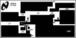
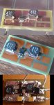
Well, this is the one i did.. Needs some finishing touches, but it should be ok..
Now i just need to compare sizes.... How big is yours?


H-S is supposed to be the area for mounting a HeatSink. I also made some notches into larger planes, to make it more obvious, where the connections are supposed to be.. The notches are only two pixels deep, so they shouldn't impair anything..


The only thing it lacks is the FeedBack line, because i wanted to draw it on the upper plane.. Better add some markings, where it's supposed to be..


Finally, etching can begin...


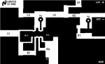
EDIT: This is the finished version.. What do you think?
Ups, i forgot to add some exposed "dogbone" to the right of the IC...
 

Attachments

  • LM3410_-_EVAL_BOARD_COPY_-_Finished_-_small.JPG
    LM3410_-_EVAL_BOARD_COPY_-_Finished_-_small.JPG
    16.1 KB · Views: 190


phenol

0
Joined
Oct 30, 2007
Messages
533
Points
18
The 5819 has an even higher forward voltage (5.5V).. The 3410 datasheet specifies a diode with only 0.4Vf and it also says, that this diode can be the source of most of the efficiency losses, if not selected properly..
i have 1n5819's from two manufacturers with different drops /i measured them/ - 0.53V and 0.43V at 1A. apparently, im using the second one
 

IgorT

0
Joined
Oct 24, 2007
Messages
4,177
Points
0
Damn.. My board is too big. 52 x 23mm... :(

Guess i'll try yours, Woop...
I just printed yours, and wow! I can't believe, how small you made it!


Well, i decided to try to make mine smaller, and it came down to 31.7 x 19.2mm..  Now it's just the right size.. Again i made some tiny "notches" in the middle GND stripe under the IC, to minimise the chance of a short.


Took me most of the afternoon, to get it perfect, so i'll have to etch tomorrow..


But i did get a perfect printout on the printable-label backing sheet, after i scratched the old ink off and cleaned it with a dry paper towell. Now the ink sticks during printing, but it will still transfer perfectly. (I hope)...
 

Attachments

  • LM3410_PCB_MINIATURIZED_EVAL_BOARD_W_NOTCHES.JPG
    LM3410_PCB_MINIATURIZED_EVAL_BOARD_W_NOTCHES.JPG
    20.4 KB · Views: 261

woop

0
Joined
Nov 9, 2007
Messages
342
Points
0
cool. I made mine smaller by changing the position and orientation of the capacitors.
the inductors came today! so now i have most of the parts. i hope tantanium capacitors will work.
I also made the heatsink for my board a big bigger on the left.
now i am going to print it and try etching

btw the ziped bitmap and attached GIF are reversed, ready for printing
 

Attachments

  • lm3410_board2print.GIF
    lm3410_board2print.GIF
    6.9 KB · Views: 189

woop

0
Joined
Nov 9, 2007
Messages
342
Points
0
I etched 3 boards successfully!
I am very pleased with myself :)
 

Attachments

  • P1010890.JPG
    P1010890.JPG
    66.9 KB · Views: 191

drlava

0
Joined
Mar 7, 2007
Messages
1,152
Points
0
that looks very good! I just finished mounting and testing the DFN-8 mackage on my toner transfer proto board, and it was not cake. However, these things are slick! Such high frequency operation makes for a very smooth output with relatively small components.
 

IgorT

0
Joined
Oct 24, 2007
Messages
4,177
Points
0
woop said:
I etched 3 boards successfully!
I am very pleased with myself :)
You should be pleased with yourself.. Looks very good.. I see you added some heat sink area..
I like it how simple your boards are.. I firmly believe, that simple is always better.. It also means there are no thin lines..  Can't wait to see if fully populated.. You should make a pic next to a ruler..

I'm gonna try yours, when i get the tiny inductors.. Right now they are too small, that's why i spent so much time miniaturizing mine, to get it somewhere in between..


And you already have the correct coils. Lucky bastard... Coilcraft aprooved my sample order, but it was for pretty much all ICs except for this one... I told them in between, that i want to change it, but they just sent the original one.. So i made another order. Wonder if they'll stall for yet another week.

This means i'll have to improvise till then.. But my engineer says the coils from Conrad should work just as well, at least that's what their datasheet says..
 

IgorT

0
Joined
Oct 24, 2007
Messages
4,177
Points
0
drlava said:
that looks very good!  I just finished mounting and testing the DFN-8 mackage on my toner transfer proto board, and it was not cake.  However, these things are slick! Such high frequency operation makes for a very smooth output with relatively small components.

DFN-8? What IC are you using?
 

woop

0
Joined
Nov 9, 2007
Messages
342
Points
0
so can anyone tell me if tantalum caps will be ok? I scavenged some from a pcmcia modem.
I also fond some .51, .22 and .10 ohm resistors on a broken mobile phone board which might come in handy for the current measuring shunt.
so far, total cost of this project has been $30 for the syringe of solder paste.

tomorrow I will put it together
 

IgorT

0
Joined
Oct 24, 2007
Messages
4,177
Points
0
woop said:
so far, total cost of this project has been $30 for the syringe of solder paste.
tomorrow I will put it together

That's some expensive paste... How much did you get for that money?


Anyway, i just finished etching mine.. They came out surprisingly well for the first attempt. 6 out of 8 are perfect the other two have some minor imperfections, but they would still work...
This toner transfer method is amazingly good.. I mean, even those tiny letters are still visible.. This is great!
 

Attachments

  • Finished_PCB.JPG
    Finished_PCB.JPG
    20.3 KB · Views: 258

IgorT

0
Joined
Oct 24, 2007
Messages
4,177
Points
0
I'm scraping my first batch of PCBs.. Even with the notches the central GND connection is too wide. I got a short, and destroyed one IC while trying to desolder it...

Need to make the central strip thinner and fix some other minor details..
 

woop

0
Joined
Nov 9, 2007
Messages
342
Points
0
i got 80 grams of paste.
how did you solder the chip?
and i used a permanent marker to fix up the large areas, the toner tends to come off a bit on the ripples of the fiberglass under the copper.
what kind of etchant are you using?
 

IgorT

0
Joined
Oct 24, 2007
Messages
4,177
Points
0
woop said:
how did you solder the chip?
and i used a permanent marker to fix up the large areas, the toner tends to come off a bit on the ripples of the fiberglass under the copper.
what kind of etchant are you using?

Well for 80 grams 30$ is actually cheap. I also used solder paste and a hot plate, it's just that i was not patient enough..

I also had to use a marker to fix up some larger areas, and some lines as well, which caused the imperfections in some of the boards. But all in all i'm satisfied in how the first batch came out. Now i know what to look out for in the next one, and i already finished drawing the improoved version..

Unfortunatelly i won't be able to etch it untill late in the evening. Oh, i'm using natrium-persulfat for etching.
 

woop

0
Joined
Nov 9, 2007
Messages
342
Points
0
yay. it works!!!
first time i soldered the chip (in a toaster oven at 200C), one of the ground pins didn't connect properly. so i reheated it and tapped the board.
I am using tantalum caps for the input ant output filter. and a 3.8uF ceramic cap for C3. (all caps salvaged from random electronic crap)

supprisingly it works, although with only 68% efficincy with 2.9V in and 3V out at 300mA
I tested it using a 10ohm resistor as the load, which is approx the same load as a burner diode.
now i just need to get myself a real burner diode

I love it when things work first time

pics:
1 - in the oven, paste hasn't melted yet

2 - finished cooking

3 - finally working. I covered all the copper in solder to stop if corroding. it looks kinda messy because of all the soldering and un soldering of caps
 

Attachments

  • intheoven.JPG
    intheoven.JPG
    177.4 KB · Views: 193

IgorT

0
Joined
Oct 24, 2007
Messages
4,177
Points
0
woop said:
supprisingly it works, although with only 68% efficincy with 2.9V in and 3V out at 300mA
I tested it using a 10ohm resistor as the load, which is approx the same load as a burner diode.
now i just need to get myself a real burner diode
Well, it could be a lot worse actually.. You got almost 70%, which is not bad.. It's good to hear it's working.. Gives me hope.. :)

What i would be interested in, is efficiencies at different voltages, also the lowest voltage, where it can keep the current steady..


I won't be able to build mine untill tonight, because some weird people insist on celebrating my birthday.. Damn..


Anyway, how did you put on the solder paste, to prevent getting a short? I mean, since you have a very wide central GND strip.. Also, did you notice any heating up?

BTW: I think just painting the copper with a permanent marker would work agains corosion just as well, and look better.. I'll paint it green.
 

woop

0
Joined
Nov 9, 2007
Messages
342
Points
0
:p happy birthday.
I used a toothpic to apply small ammounts to the pads and the main sink pad. supprisingly no shorts, the solder has a tendancy to bead up anyway so you must be putting on a lot of paste for it to short out.

and it usually doesn't look that bad when you cover the copper with solder. i usually wipe the board with flux and then sorta paint the solder on the board, its like magic.
it only looks crappy because i had soldered and unsoldered wires and stuff. next board i will go for asthetics.

it only got hot when i forgot to connect the feedback wire :p
otherwise, after 1/2 a min of running i don't think it got hot
it wouldn't like running without a load

I will have to set up a varable power supply to test current at different voltages. it does work off 3 or 4 AA nimh and it should work off 2 alkaline AA's. lowest voltage it will work off is 2.7V, then the freq drops and current rapidly drops off
also with the following modification it will work off 2 ni-mh AA or AAA's. next board i make will include that
 

Attachments

  • bootstrap.JPG
    bootstrap.JPG
    23 KB · Views: 211


Top