Welcome to Laser Pointer Forums - discuss green laser pointers, blue laser pointers, and all types of lasers

LPF Donation via Stripe | LPF Donation - Other Methods

Links below open in new window

ArcticMyst Security by Avery

Simple Adjustable Laser driver (V. 2) It Works!!!

Joined
Sep 8, 2008
Messages
182
Points
0
Hello All,

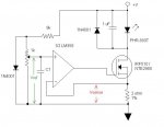
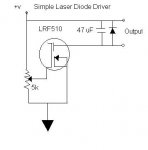
This is my first post. Apologies if this is already out there. Attached is the driver I built for my first 300mW burner. Instead of a regulator, I've used a IRF510 mosfet to control the current. The potentiometer adjusts current. As built it puts out around 400 mA when the gate voltage is 4.5 volts and the supply voltage is 9v. I'm still waiting on my host to adjust for a 6v supply. But since mosfets have very low resistance, the same circuit could be adjusted to power a 405nm diode even off a 6v supply!  

The 4 components are cheap and can easily be fit into most hosts. (minus the mosfet's heatsink in some cases)

cheers,
kernelpanic

[edit] The Mosfet is an IRF510, not an LRF510, sorry for the typo. [/edit]
 

Attachments

  • driver.JPG
    driver.JPG
    11.6 KB · Views: 3,375


Joined
Nov 24, 2007
Messages
65
Points
0
Re: Simple Adjustable Laser driver

That's pretty cool, thanks for sharing :)

If the output current varies with input voltage could you change the circuit to maintain a constant current over a wide voltage range by adding a second fet to the circuit with a current sense resistor in there somewhere connected to the gate of one of the fets as a kind of feedback?

Edit: spelling
 
Joined
Sep 8, 2008
Messages
182
Points
0
Re: Simple Adjustable Laser driver

<SNIP>
If the output current varies with input voltage could you change the circuit to maintain a constant current over a wide voltage range by adding a second fet to the circuit with a current sense resistor in there somewhere connected to the gate of one of the fets as a kind of feedback?
</SNIP>

I actually tried something similar. I connecteded a 'load sensing' resistor between the Source of the FET and ground. Thus the more current that flows the higher the source voltage is. This reduces the G->S difference and reduces the current. Negative feedback without adding a second transistor. But because the IRF510 isn't fully 'on' until G->S voltage is 10v, this reduced the current too much at lower supply voltages. I do want to try that with a logic level mosfet like the NTE2980 though as it requires only 5v gate to source. I've got some ordered right now. Once I breadboard the circuit and test it, I'll post a usable schematic...

I also think it would be neat to run a logic level mosfet off of a 555 timer with adjustable pulse width. That way one could adjust duty cycle and thus apparent brightness while still running the diode at optimal efficiency. (The end run here would be to use a signal to adjust the pulse width and thus modulate the beam. (Laser tranciever anyone?)

cheers,
kp
 
Joined
Oct 26, 2007
Messages
5,438
Points
83
Re: Simple Adjustable Laser driver

It reminds me of this design, which I thought was pretty cool as a kind of current-sink based design. I tested it in a simulator and it worked nicely.
 
Joined
Nov 24, 2007
Messages
65
Points
0
Re: Simple Adjustable Laser driver

kernelpanic said:
I do want to try that with a logic level mosfet like the NTE2980 though as it requires only 5v gate to source. I've got some ordered right now. Once I breadboard the circuit and test it, I'll post a usable schematic...

Cheers, it would be great if you could share your schematic when you get something working, if you have the time and energy it would be great if you could explain how the circuit operates in some detail. :)

Bionic-Badger said:
It reminds me of this design, which I thought was pretty cool as a kind of current-sink based design. I tested it in a simulator and it worked nicely.

I have tried that design but I used a different fet. The fet I used was an AP4800AGM, datasheet is http://www.alldatasheet.co.kr/datasheet-pdf/pdf_kor/193267/A-POWER/AP4800AGM.html. It didn't work too well, the output current varied quite a bit with input voltage so I put it aside thinking I will try it again at a later time when I have the correct fet to try it with.
 
Joined
Sep 8, 2008
Messages
182
Points
0
Simple Adjustable Laser driver V2

Hello All,

Here's the next iteration. It's not quite as simple. But it incorporates current sensing to limit output rather than rely solely on the potentiometer. This is an ultra low-dropout circuit optimized for running a 405nm diode in a 6 volt host.

Here's how it works-
The 9k resistor, 1k pot provide our adjustment. At 6V the max voltage into the noninverting input is 0.6v The diode keeps this stable for variations in supply voltage and can be omitted if one is not switching back and forth between rechargeable (7.2v) and non rechargeable(6.0v) sets of CR123's. The inverting input is connected to the 2 ohm current sensing resistor. When voltage is applied to the circuit, the voltage into the noninverting input of the lm358 causes the output to rise and turn on the mosfet.  As current flows throught the load, the voltage across the 2 ohm resistor will rise until Vsense = Vref. In this manner current is limited.

To set the current turn the pot until- Vref = Desired Current * 2. So for 140mA one would set Vref to  0.28V.

Q. Why is the output capacitor only 1uF?  

A. This isn't a switching driver, so ripple is minimal. I think using a big capacitor here increases rather than reduces the number of blown diodes.

Q. What size capacitor should I use for C1?

A. I don't know yet. C1 has 2 purposes, to prevent oscillation and to slow down turn-on. It's value is not critical and can be determined experimentally.

CAVEATS-
1. Using a mosfet allows the circuit to deliver almost full supply voltage to the diode while limiting current to desired values. But this driver is only efficient if the diode voltage is close to the supply voltage. (i.e.- running a red diode at 2.9V off of a 12V supply would dissipate the remaining 9.1V in the mosfet and be only ~20% efficient. But running a 5V blu-ray diode off a 6v supply can hit 80%. This circuit could be modified to run red diodes off a 4.5V supply, but only using a logic-level mosfet.

2. This is a 405nm supply only for one obvious reason- The cathode pin on the PHR-803T diode is not case grounded. The 650nm diodes have a case-grounded cathode which will bypass the regulator circuit in a metal host blowing the diode!!!

Again- Do Not use this driver with red diodes in a metal host!


3. I have not actually built this exact circuit yet. I will be doing so tomorrow (once I procure a single rail op-amp) and run it with a test load. Once I've tuned it, I'll post back. Until then if you breadboard this remember it's untested...

cheers,
kernelpanic

[edit] As shown the max output current is ~300mA. [/edit]
 

Attachments

  • driver-new.JPG
    driver-new.JPG
    27.8 KB · Views: 13,101
Joined
Nov 24, 2007
Messages
65
Points
0
Re: Simple Adjustable Laser driver (Version 2)

Hey, nice work. :) That circuit looks great, so it looks like this circuit will work with pretty much any n channel fet that has a gate threshold voltage that is within the supply range of the batteries we are using and will handle the current. If that's the case, then I will have to have a crack at this on the weekend (long weekend :)). I have some fets but not the one you have specified in your circuit.

I notice that if you have a 7.2v supply, if there was no diode across the 1k pot and the pot was set to maximum value, the voltage at the non inverting input would be 0.72V and would reduce as the batteries depleted. Does the diode across the pot limit the maximum voltage at the non inverting input to the opamp to 0.6V? I'm still trying to get my head around opamps and such, although this is probably more of a voltage divider question :)

Again, thanks for sharing and giving such a thorough explanation.
 
Joined
Sep 8, 2008
Messages
182
Points
0
Re: Simple Adjustable Laser driver (Version 2)

I notice that if you have a 7.2v supply, if there was no diode across the 1k pot and the pot was set to maximum value, the voltage at the non inverting input would be 0.72V and would reduce as the batteries depleted. Does the diode across the pot limit the maximum voltage at the non inverting input to the opamp to 0.6V?

That's the idea exactly. The problem I had with the first driver was that the current limiting was relative. Changes in supply voltage, temperature, etc. changed the output current. This revision gives us a Vref and Vsense that are (mostly) independent of supply voltage.

This circuit basically works because op-amps will automagically try to make the inverting input and noninverting input match through the feedback loop. Since we've brought the load current into the feedback loop, the current regulation should **just work** . The op-amp will increase the gate voltage applied to the mosfet until the voltage across the 2 ohm resistor equals the reference voltage. To get the current we use Ohm's law- I = E / R. (E being Vsense and R being the 2 ohm resistor...)

If you build this, definitely post your results. As I said before, I haven't built it yet myself. It may require tuning. So caution and testing are in order before risking any diodes...

cheers,
kernelpanic

p.s. Not any op-amp will do for this circuit. It needs to be a single rail amp like the lm358/lm324. But for the mosfet, any N channel enhancement mode mosfet that can handle the power should work. * But a logic level mosfet should work better...  ;)
[edit]
Tuning Ideas/Guide.-
- Changing Rmax (the 9k) will change the current drawn by the Vref diode.
- Changing the pot/Rm ratio will alter the max current as follows-
    Imax = Vs * ( pot / Rmax ) / Rsense
- Rsense should be as small as possible to increase efficiency and to allow the use of smaller components. But  it needs to be large enough to allow adequate current control. It may be possible to use a 1 ohm for 405nm. It is important to consider how much power this resistor will need to dissipate. At 200mA a 2 ohm  resistor will drop 0.4v for TDP of 0.08 watts. At 300 mA is will drop 0.6v for a TDP of 0.18 watts. For 650nm, at 420mA a 1 ohm resistor will drop 0.42v and dissipate 0.18 watts. (We're trying to use smaller resistors as space is limited...)  So to tune for 650nm one would use a smaller resistor for Rsense, and select values for Rmax and the pot that give us our 0.6V. So to get Imax = 600mA we might do:
  Rmax = 6.5k
  Pot    = 1k
  Rsense = 1 ohm 1/2W 1% (TDP @ 600mA 0.36 watt)
(Note- Practically speaking one would also have to reverse the circuit and use a P channel mosfet to keep  the case ground on the diode from bypassing the circuit for 650nm diodes...)
[/edit]
 
Joined
Sep 8, 2008
Messages
182
Points
0
It Works!!!

Hello All,
I did get a chance to breadboard this circuit. I tried it with a few different mosfets. Both the normal mosfets and the logic-level one I tried worked great on a test load with a 9v supply. But for 6v or 4.5v supplies, the logic-level mosfets are the way to go for sure. I used an IRL520 with great results. The op-amp keeps the 'sense' voltage equal to the 'reference' voltage. With a 1 microfarad capacitor for C1 response is smooth. I'm waiting on a phr-803t. Once I get it, I'll post pics ;)

I'm thinking the circuit could be built pretty small. The lm358 is available in 8 pin SOIC. And the IRL520 is way overpowered for what we're doing. The 'in-host' circuit will likely use an NTE2980 and the SOIC packaged op-amp. The fixed resistors can be surface mount and the pots I use are TINY...

This is not a 'Universal' driver. The circuit as posted (with an IRL520 or other LL mosfet) is tuned for running 405nm diodes off of 6v. It can be tuned to run any supply voltage or current. But the design in general is best suited for low-dropout applications where the voltage needed by the diode approaches the voltage supplied by the battery. Also component values must be tuned for the supply voltage and also for the max-current. But it looks very promising if you want to drive your blu-ray off of 6v, your open can off of 4.5 (or possibly even your 808nm off of 3.6, more testing  needed...)


Anyhow if you want to build this, use any N channel enhancement mode logic-level mosfet (IRL520, NTE2980-2987, etc.) that can handle the current and you'll be fine. Also, use a 10 turn pot for best control and a 1%, 1/4 W resistor for the 2 ohm. Most importantly, DON'T GROUND the phr-803t cathode to the chassis of your host!!! Current regulation happens between the cathode and the ground. So a solder bridge on your LD can spell death... You have been warned. With that in mind, this driver works great.

Stay posted for more!

cheers,
kernelpanic
 
Joined
Sep 8, 2008
Messages
182
Points
0
Re: Simple Adjustable Laser driver (V. 2) It Works

Hello All,

Here's a progress report. I've managed to build this small enough to fit in the SKU4171 host. (Pic included) However it's a tight fit. So I ordered all of the parts from digikey to build this surface mount. I ordered enough to build 10. I'll probably murder the first one or two until I figure out the best layout.

Anyway here's a shot of the breadboard and of the assembled supply next to the host. I apologize for the low quality. (cell phone) When I get home I'll take a better close-up...

Cheers,
kernelpanic
 

Attachments

  • la_dr.jpg
    la_dr.jpg
    151 KB · Views: 1,215
Joined
Sep 8, 2008
Messages
182
Points
0
Better Picture...

Hello All,

Here's a better picture of the assembled driver in-host. I've run it quite a bit under a test load. I have to say it provides the regulated current all the way up to 98% of supply voltage. For low-dropout, mosfets are the way to go. The op-amp and pot  only eats 20-25mA, the sense resistor only pulls a small (~2%) amount, and the mosfet dissipates- I[sub]load[/sub] *  (V[sub]load[/sub] / V[sub]in[/sub]) watts.

So at 6V and 150mA, The op-amp will use 25mA***, and the rest will use 150mA for a total of 175mA at 6V for a TDP of 1.05 watts. If it delivers 150mA at ~5v, then it is giving out 0.75 watts. The mosfet is only dissipating 0.15 watts! Running a 6 diode test load off of 2 cr123's @ 150mA the transistor  barely gets warm! (This is with the heat sink cut off even...) Running 7.2v rcr123's will give 1.25 watts TDP with 0.75 out still and the mosfet dissipates 0.33 watts. Not quite as good, but comparable to the LM317... Basically, this mosfets are at their most efficient when all the way on or all the way off. So a driver like this will get more efficient the higher it is turned up and the closer the diode voltage is to the supply voltage. I have high hopes for red and IR diodes at lower supply voltages if I can find the right P-channel mosfet...

Should have my next diode (read- victim) tomorrow. Once I get it in a module, I'll hook it up, cross my fingers and post results/pics.

cheers,
kernelpanic


***Note the number quoted for op-amp draw is a bit large. It's only driving the mosfet which is an extremely small load, and we're only using half of it. My ammeter is shot at this time (needs fuse) but with both amps in the LM358 running full blast it only draws 40mA max. So one amp running lower may only draw 15mA...
 

Attachments

  • ld-inhost.jpg
    ld-inhost.jpg
    83.7 KB · Views: 810

jake21

0
Joined
Dec 2, 2007
Messages
3,189
Points
0
Re: Simple Adjustable Laser driver (V. 2) It Works

are u selling a driver ?
 

rkcstr

0
Joined
Dec 1, 2007
Messages
1,368
Points
0
Re: Simple Adjustable Laser driver (V. 2) It Works

I think at this point, he's still developing his circuit, probably a ways off from selling something.
 
Joined
Sep 8, 2008
Messages
182
Points
0
Re: Simple Adjustable Laser driver (V. 2) It Works

rkcstr said:
I think at this point, he's still developing his circuit, probably a ways off from selling something.

You are absolutely correct. ;) (That's why we're in the 'Experiments' topic...)

I'm simply trying to build a cheap DIY circuit capable of lower dropout than the LM317. It's posted here in case anyone else wants to build it. Once I get the surface mount version done, I'll likely post the PCB pattern. If one wants to build a driver and this fits your needs, great! But if one is looking to purchase a driver, rckstr or drlava both have proven drivers. Mine is at this time experimental...

cheers,
kernelpanic
 

Zom-B

0
Joined
Mar 25, 2008
Messages
895
Points
28
Re: Simple Adjustable Laser driver (V. 2) It Works

I haven't seen this thread before, so I might drop in a little late

My adjustable lab driver is almost the same as your second iteration. I an using a heatsinked darlington (which gets pretty hot at 420mA after a duty cycle of just 30 seconds) and I was planning on using a BUZ11 mosfet but never got around to testing it. I don't know if they are suited for low dropout applications but this one was recommended to me by an electronics student while improving the schematic together.

This is my V3 driver (V1 never existed). It has not yet been tested and the resistor values of the current selection in the lower left are not yet calculated (values are random). Maybe I'm also going to include a startup delay with one of those tiny PIC10s.
Labdriver.png


Notice that my cap is between the output and input of the opamp. In this case, when the opamp increases it's output in order to equalize it's inputs, it pulls it's sense input up with it, so it will slowly rise until the cap is charged via the sense resistor.

Any ideas, on ANYTHING, are appreciated. For example, I'm also unsure about my redesigned power supply part.


Photos of my V2, currently in use
hpim3954.jpg


hpim4041_small.jpg


Hpim4262.jpg

(only the leftmost red laser is driven by it :))
 
Joined
Sep 16, 2008
Messages
48
Points
0
Re: Simple Adjustable Laser driver (V. 2) It Works

Good god Zom-B . Nice multilayer setup you got there. Are those the MW's listed on each aixiz module?


Top