- Joined
- Jan 14, 2011
- Messages
- 3,816
- Points
- 63
Hey everyone.
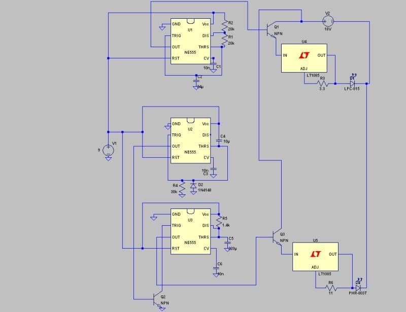
So I recently had an idea... I have been toying around with building a neato spirograph for a while now, but then I realized... why not just build one with three colors in it? All it would require would be a dichro and an extra diode (would use a PHR and an LPC).
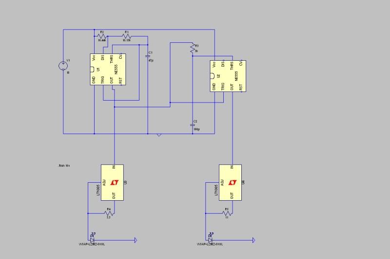
Except... I would also need a method of having it pulsed between three colors. Now, I thought that the easiest way to do this would be have some sort of 555 timer or something periodically pull a transistor, then two transistors in series (?) then have it set back to 0V output, so that it would cycle between red/magenta/blu-ray, because I think that would be really neat to be able to get a spirograph that changes colors.
However, I have no idea if what I thought of would work, or even if it would work, how it would work.
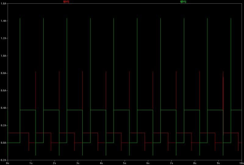
The idea is that off mode would be red, then one transistor on would turn ON BR (giving magenta), then the second one would switch OFF the red, giving just BR, and then it would cycle like that, probably at .5Hz or something.
But I am not sure how to go about making transistor gates go in SERIES... so that the voltage is added between them.
Anyone have any ideas?
(Of course, these transistors would just turn on/off the normal drivers I would have to be powering these diodes, which would probably be an easy LM1117 build or something. And I would have power knobs for fine tuning, etc.)
So I recently had an idea... I have been toying around with building a neato spirograph for a while now, but then I realized... why not just build one with three colors in it? All it would require would be a dichro and an extra diode (would use a PHR and an LPC).
Except... I would also need a method of having it pulsed between three colors. Now, I thought that the easiest way to do this would be have some sort of 555 timer or something periodically pull a transistor, then two transistors in series (?) then have it set back to 0V output, so that it would cycle between red/magenta/blu-ray, because I think that would be really neat to be able to get a spirograph that changes colors.
However, I have no idea if what I thought of would work, or even if it would work, how it would work.
The idea is that off mode would be red, then one transistor on would turn ON BR (giving magenta), then the second one would switch OFF the red, giving just BR, and then it would cycle like that, probably at .5Hz or something.
But I am not sure how to go about making transistor gates go in SERIES... so that the voltage is added between them.
Anyone have any ideas?
(Of course, these transistors would just turn on/off the normal drivers I would have to be powering these diodes, which would probably be an easy LM1117 build or something. And I would have power knobs for fine tuning, etc.)