Welcome to Laser Pointer Forums - discuss green laser pointers, blue laser pointers, and all types of lasers

LPF Donation via Stripe | LPF Donation - Other Methods

Links below open in new window

ArcticMyst Security by Avery

PT-121 Testing

rhd

0
Joined
Dec 7, 2010
Messages
8,475
Points
0
Keep in mind that the linear 1085 based "DDL" style drivers we use to drive 1.8A 445nm diodes are basically using two resistors to get a voltage drop reference of 1.25V. That's a bit above 1 W of dissipation, and those are typically 2512 resistors rated for 1W (maybe 2W).

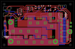
The guys I linked above (2728 package), have 2.5X the surface area of a 2512 package resistor, and they're being required to drop a bit less heat too. As weird as it sounds, you can actually heatsink them too. The way I've laid them out on this board, you can arctic silver one thin aluminum strip across all of them (between the contacts of course) and that will raise the elevation enough that you could then stick a tiny heatsink across all 4 at once, without any risk of shorting. That said, I really don't think it will be needed based on what I've observed with much smaller SMD resistors at a similar power dissipation (inside closed hosts as well).

Here's a revision. Additions, other than the resistor update, are a ton of beefier planes for the current to travel. Now that I have a way to drive one, I'll probably grab a diode bar at some point. Once I do, I'll actually get these PCBs made. I need to do 10x at a time, so if anyone else wants one, they're more than welcome to it (that is, with Mosc's permission).

attachment.php


The one thing I would add before making this, would be the ENABLE feature. I'll have to wrap my mind around Mosc's suggestion as to how to implement it, and see if it can be worked in without requiring any major re-routeing of the board.
 

Attachments

  • Untitled-1.png
    Untitled-1.png
    96.3 KB · Views: 420


Joined
Feb 2, 2012
Messages
577
Points
43
Those resistors are probably fine.

I am just not used to tiny parts dissapating so much heat. I am used to larger style PCB's with larger components.

I just don't like things running hot. Even though it's the norm today. We were always taught the hotter something runs the shorter it's life span.

Hard to accept that the Resistors I used have the same rating as the ones you are using.

The Free sample arrived today. That was damm fast. They sent it FedEx Express International. I will probably get the Blue one done tonight.


Charles
 
Last edited:

rhd

0
Joined
Dec 7, 2010
Messages
8,475
Points
0
Keep in mind that a Watt is a Watt, right?

So two resistors of the same resistance, pumped with the same current, are going to dissipate the same amount of heat. So at least as far as "running hot" goes, any combination here will create the same amount of heat.

What I like about your approach, is the increased surface area for heat dissipation. In fact, I actually like that style of resistor a bit more too - it could sort of "jump" across other components on the board. There might also be a benefit to not dissipating as much heat into the PCB itself. Is this the one you used?
Digi-Key - BR3FB5L00-ND (Manufacturer - BR3FB5L00)
 
Joined
Feb 2, 2012
Messages
577
Points
43
That is kind of correct. Watts are Watts. But the Heating effect is not the same.

It's the heat dissapation abilitly. Small components don't dissapate heat very well. Large components do dissapate heat very well.

The Resistors I use only just get slightly warm. The Surface mount ones would get very hot because they can't dissapate the heat as well as the larger ones.

Different supplier but they look like the same ones.


Charles


Keep in mind that a Watt is a Watt, right?

So two resistors of the same resistance, pumped with the same current, are going to dissipate the same amount of heat. So at least as far as "running hot" goes, any combination here will create the same amount of heat.

What I like about your approach, is the increased surface area for heat dissipation. In fact, I actually like that style of resistor a bit more too - it could sort of "jump" across other components on the board. There might also be a benefit to not dissipating as much heat into the PCB itself. Is this the one you used?
Digi-Key - BR3FB5L00-ND (Manufacturer - BR3FB5L00)
 
Last edited:
Joined
Feb 2, 2012
Messages
577
Points
43
I put together the Blue PT-121 and am running it at 30 Amps. Should be 750 Lumens.

No Reflector. Just raw light output.


Blue1.JPG


Blue is nice. Their does seem to be a LOT more heat from the LED Glass with Blue. I suppose because it's so inefficiant compared to Green. 3500 Lumens Green and 750 Lumens Blue
at the same Current. LED Voltage is slightly lower than Green. The input power is around 120 Watts. Don't know if I want to run the Blue at 30 Amps for too long. Green seems fine at
30 Amps even though the input power is higer. It's just so much more efficiant.


Charles
 
Last edited:
Joined
Feb 2, 2012
Messages
577
Points
43
Been having a bit more of a play with the Blue.

I am not so sure now that the Blue is running Hotter than the Green. I need to use a Temperature gun to check it or try and connect wires to the Thermistors. The Power Terminals feel the same Temperature as Green. I can easily leave my finger on them.

I think what is happening is that my Hand is Absorbing more of the Blue light than is absorbed by Green. Making the Blue light feel hotter.

Even at several inches in front of the Blue LED if I hold my Palm in front of the Light my Palm feels very warm to hot.


Does anyone know the differance between "Peak Luminous Flux" and "Peak Radiometric Power" ?

Green is 7.3 Watts and Blue is 16.3 Watts for "Peak Radiometric Power".


Charles
 
Last edited:
Joined
Feb 2, 2012
Messages
577
Points
43
Been doing some research.

I didnt know that Lumens are based on the color response of the human eye. That explains why green is 3500 lumens and blue is 750 lumens for the same LED current. Because our eyes are much more sensitive to green than blue.

I guess this makes sense. It means differant colored lights with the same Lumen output appear the same brightness to our eyes.


The radiometric power is the Real output power in Watts without useing the Human eyes color response.

Based on this the Blue light feels so much hotter than green because the output power of the Blue is 16.3 watts and the Green is only 7.2 watts.

That means the Blue LED is actualy much more efficiant than green in terms of real output power in Watts.

I also assume my hand does still absorb more Blue light than Green.


Charles
 
Last edited:
Joined
Feb 2, 2012
Messages
577
Points
43
Here's a revision. Additions, other than the resistor update, are a ton of beefier planes for the current to travel. Now that I have a way to drive one, I'll probably grab a diode bar at some point. Once I do, I'll actually get these PCBs made. I need to do 10x at a time, so if anyone else wants one, they're more than welcome to it (that is, with Mosc's permission).

Sorry I missed that request.

Of course you can get boards made. Anyone in this Forum is welcome to use my design.

Any improvements are also welcome.


Charles
 
Last edited:
Joined
Feb 1, 2008
Messages
2,894
Points
0
Very cool! I'm going to have order one of those samples ;)

I ordered 3 slightly different model numbers (differences in max temp and lead content), and I actually received 4 total boards just today!

One question would be, is if these are still parallel-able when using the tracking pin for constant current. One would think you could send feedback into both boards at the same time, and expect similar current flows that could be directly paralleled.

Bad idea?
 
Joined
Feb 2, 2012
Messages
577
Points
43
I doubt they would parallel very well in Current mode. The Module is still running in Voltage mode. The Output voltage is set by the Current Regulator. If one Module had slightly more output volts than the other it would carry more current.

One option that would probably work is if each module had its own Current regulator. Then the outputs are paralleled.

You would need to divide the Current Ref by the number of modules though. If you wanted 60 amps and you had 3 modules you need to set each module to 20 amps.


Charles
 
Last edited:
Joined
Feb 7, 2012
Messages
977
Points
0
Very kewl.. No one lets me play with green yet.. (Meatgrinder) but DTR let me have a blue and I have been trying to find a way to dive these over and above my 5A PSU... I Laughed at the eagle files over my own stupidity!.. Nice work!
 
Joined
Jun 23, 2012
Messages
1
Points
0
Mosc did you ever get a chance to take some outdoor shots with that green monster you built? I would love to see how well that baby lights up a large area. :pop:

I am wanting to build a fixed light for shining off our fishing dock for attracting fish here in Texas.....green is the best color for attracting baitfish and light penetration into the water will be fantasic with the PT-121 I think! I would need the unit to stay on for at least 6 hours per night and be mounted much like a "streetlight-type" enclosure with the driver and transformer in a dry location at least 20 feet away. I am thinking the wire from the driver to the led housing will need to be pretty beefy.....8 gauge? :thinking:

I am having a bit of trouble following your build because I have no experience with LED and this is an unusual project, but it looks like I need:

X Phlatlight PT-121
X Heatsink and Reflector
X 12 Volt Power Supply
X A handbuilt driver to keep the thing from overheating while driving up to 30 amps at around 5 volts.
X a photocell and timer to turn this on and off when unattended

I will keep reading to learn what I can but anything you can offer for me to jump-start my quest would be much appreciated!

I guess my first step is to locate that PCB?..... I didn't notice any product IDs for the components you used. This being my first project is going to be more of a Paint by Numbers deal for me, but I really like this stuff. My son and I have been drooling over the laser builds we have seen on this site!

My wife is getting frustrated with my OCD researching of this project.......help! lol
 
Joined
Jan 14, 2011
Messages
3,816
Points
63
Sorry for the necropost, but I have a related question.

So I ended up building a slightly varied version of this driver to power a 40W 808nm laser diode bar.

It seems to work... except that the pot isn't adjusting the current. I have a 2.5V shunt diode instead of the 5V, but I have reduced the sense resistors by a factor of 2 to compensate. I also removed the 68k resistor so that it doesn't shut off when the voltage sags - it wasn't running at all before I took that resistor off.

For some reason, the tracking pin is seeing 6+V instead of the .9V or so that it should be seeing (my test load is a .02 Ohm resistor). Anyone have any clue what could be wrong with it?
 
Last edited:
Joined
Oct 26, 2007
Messages
5,438
Points
83
Why did you change the sense resistors? It's configured for CC mode, so unless you're trying to affect the current range you probably shouldn't touch those resistors.


Top