Welcome to Laser Pointer Forums - discuss green laser pointers, blue laser pointers, and all types of lasers

LPF Donation via Stripe | LPF Donation - Other Methods

Links below open in new window

ArcticMyst Security by Avery

Power curves

Joined
Jan 7, 2007
Messages
6,309
Points
83
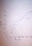
I've posted several times about graphing your diode I(current) vs P output to find the knee of the curve. This is one way to find where your LD is crapping out and will give you no more. Beating the LD with current until output improves doesn't hold here.
I graphed two diodes today with my TEC cooled module. I did this by hand using my LPM-1 power meter in 50 mA steps.
The lower curve is a SenKat GB diode and the higher one is an open can harvested from a 20x DVD. Note the differences !! The GB is more efficient up to about 200 mW but the open can has a poorer efficiency slope up to 300 mW.

I hope this graph comes through OK. It shows where to back off !!! Every LD is a little different and will have a different curve by a little bit.

Mike
 

Attachments

  • Graph1.jpg
    Graph1.jpg
    10.2 KB · Views: 181


Kenom

0
Joined
May 4, 2007
Messages
5,629
Points
63
so lets see if I understand this correctly.  Your Gb diode shows a knee at about 350-400ma  closer to 400ma and the open can has a knee around 550ma-600ma.  Correct?
Graph is a bit hard to see good thing there is zoom in IE7

If this is the case I find it odd that I keep getting around 150-170mw of power from 350ma from these GB diodes. I don't have the understanding right now nor the time to build one of daedals circuits to change the output on these nor do I think it would fit well inside of the Dorcy JR. this is why everyone is using much larger hosts than what I prefer.
 
Joined
Jan 7, 2007
Messages
6,309
Points
83
I'd keep the GB diode at 300 mA or less -- All you will get is heat.  At 250 to 300, the output will do the fun stuff. If you don't have a power meter to do this test, stay about 250 mA as recommended.
 Remember, my test here is TEC cooled.

This particular open can starts leveling off at about 500 mA -- No good to go farther.

LD's all vary on their curves and If you are going to push the crap out of one, you should find the point of no more power.

Mike
 

Kenom

0
Joined
May 4, 2007
Messages
5,629
Points
63
but I was close in the understanding of how to determine the diodes knee? What are you using to change the power output on this at 50ma increments? Is it a lab power supply? Can you do the same thing with Daedals circuit?
 
Joined
Jan 7, 2007
Messages
6,309
Points
83
Kenom --

Yes -- DDL's circuit is still a super current source and it will let you increment in 50 mA steps. Simple and highly recommended. I'm using the L200 regulator chip which lets me set max current or voltage. One device, two pots and a few parts.

Yes you did see the knee where things just turn to heat. I notice that we've been saying 250 mA for the GB diodes -- now you see why !! 250 mA is about the last straight part of the curve. True you can get a little more but for those who bought only 1 or 2 ---- STOP and enjoy ;D I bought several of these diodes and highly recommend them especially if you are planning to go to higher power or the 'Blu-Ray !!!!!

Mike
 

Benm

0
Joined
Aug 16, 2007
Messages
7,896
Points
113
Very nice to see these measurements! Little use to push the GB diode over 300 mA i guess... a good thing to know, since i won't have to push it any further since it won't give more power. I reckon it did survive your testing to 450 mA?

Btw, it's been ages since i've seen a graph made like that. You must adore ye'olde user interfaces ;)
 
Joined
Jan 7, 2007
Messages
6,309
Points
83
Benm --

Thanks for the comment on the graph. That's how we did it back in the slide rule days !! It still shows the info - YES I did use my old French curve to draw the lines !!!! Remember -- this technology took man to the moon and back.....

I wouldn't go for the 300 mA unless you have heatsinking -- Then again -- they're all a little different and you may have the diamond of the lot !!!!

I'm sticking to 250 mA as posted many times for anyone beginning here. If you think you need about 20 more mW -- go for it but have spares like me. Yes I did push to 450 mA to show how level the line becomes. I could have pushed the open can to 700 mA but to what purpose.


Mike
 

Benm

0
Joined
Aug 16, 2007
Messages
7,896
Points
113
Those GB diodes are amazingly user-friendly if you ask me... 450 mA is almost twice the useful current and they still live.

I think i actually hit one with 700 mA or so today for a split second due to miswiring in the driver - it seems allright but i'm not sure how bad the current spike was... that was one advantage of those analog multimeters where you could see how far the needle went even for a brief moment ;)
 
Joined
Jan 7, 2007
Messages
6,309
Points
83
Benm --  Analog - Digital ----  They all have delay in feedback readout.  You'd need a O'scope to track spikes like that.   Few here have a 'scope.

This is where you need an adjustable current source and go slowly.  OOPsies don't count here   ;D ;D

Again --450 mA appears surviveable but you get no additional output.  If you heat those little wires inside the can, will you get IR ???  (that's a joke)

Mike
 
Joined
Feb 8, 2007
Messages
609
Points
0
Mike - the curves definitely show a trend similar to what I'm getting. Thanks for running the data!!

I'm using the diodes from the group buy and am consistently getting 250-260mW peak and 215-225mW stable output with only a 5 ohm resistor and 2 cr123 batteries as the circuit.

going to 7.5 ohm reisitor I'll get around 215-225mw peak with 195-200mW stable.  

I am using lots of heatsinking and can attest that the 5 ohm setup causes a premature death (less than 24 hours of on time) but I left them on for over 35 minutes at a time with no loss of power.  Duty cycle would probably improve survival.
 
Joined
Jan 7, 2007
Messages
6,309
Points
83
Steve ---
I don't run them too long at that high current. I will try sometime as
I have a few to spare !! But at least the curve shows why 250 mA is about
right for the GB diode. My tests are also TEC cooled.

Mike
 

JES

0
Joined
Aug 24, 2007
Messages
48
Points
0
Love the data Mike. I would have grabbed the French curves too.

Did you grab any temp readings? How cold do you push that TEC?
 

Daedal

0
Joined
May 23, 2007
Messages
2,277
Points
0
Mike... you are the man! That is the one of the best posts I have seen on here in a while :D

Being able to somewhat judge what output you're getting based on the input current is priceless. I would also suggest, based on the beautiful ::) curve there that 250mA is a very safe a solid spot for these diodes. Although not all diodes follow the same path, and not everyone here will be running theirs with a TEC, this is by far the most informative graph I've seen on here. It matches the spec sheet very nicely.

Thank you very much;
DDL

P.S. I will add this to the sticky post up top for you :)


Top