

- Joined
- Feb 5, 2008
- Messages
- 6,252
- Points
- 83
OK all you LPF members reading this,
How many of you still have soldering irons for 5$ ?
How many of you wanted 100$/200$ soldering station?!
Holy shit that is a lotta hands...
Well, I have a solution for you! That is, if you are willing to put effort in it.
Like many others, I'm still stuck with 4$ soldering iron, for simple reason, I cannot afford anything better. Well I'll be damned if I ain't having my moments of luck from time to time... I will not bother you with the story of how i got hold of 1993 year magazine Erwo, in which there was a schematic... Rather interesting one.
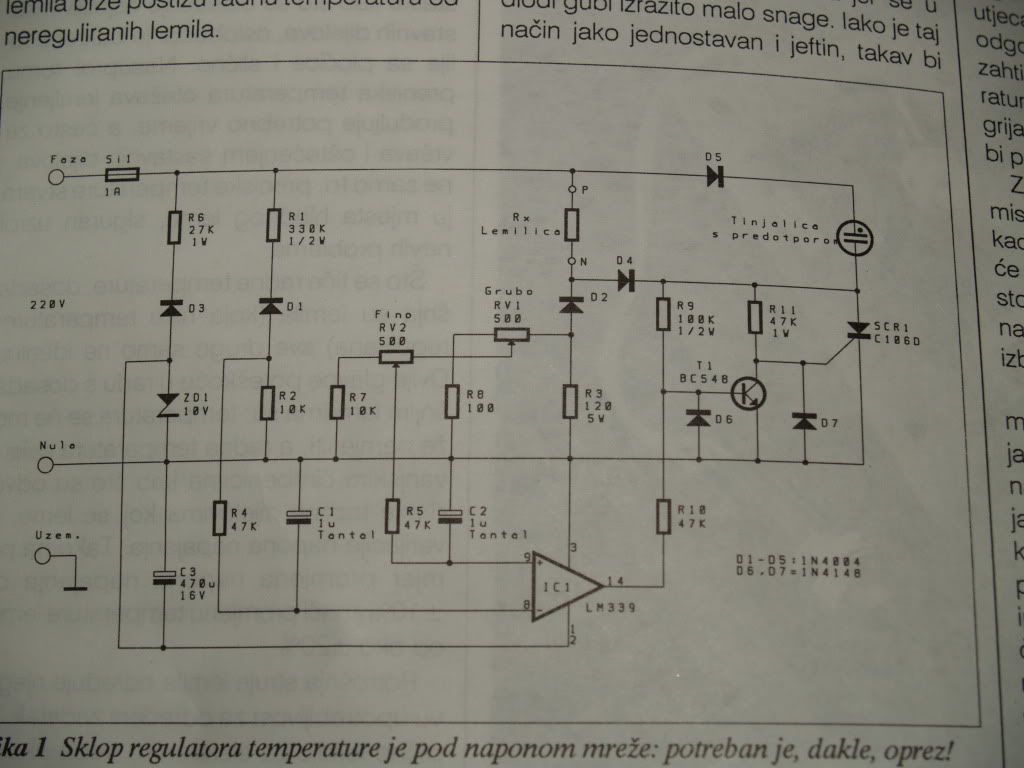
Allow me to interpret the text that accompanies the schematic.
Soldering stations temperature is regulated from the feedback of the probe inside the tip. That is one expensive tip.
If you were to do something on that scheme, you'd encounter many problems. First, as most common thermistors and silicon diodes (used to measure the temp) are not able to withstand such high temperatures, choice falls on the more expensive and hard-to-get probes.
But even if you were to get them, problem is installing them. That alltogether represents massive change of good old soldering iron.
So how to get the feedback? Phisics science is giving us the answer right in the middle of the iron: The heater!
The heater itself is nothing more that coil resistor. That means it also has all the properties of the resistor! With the change of temperature, it changes it's resistance.
Therefore, you are spared of buying expensive probes/tips/handles.
You do not need to modify the soldering iron at all!
Now, for the schematic
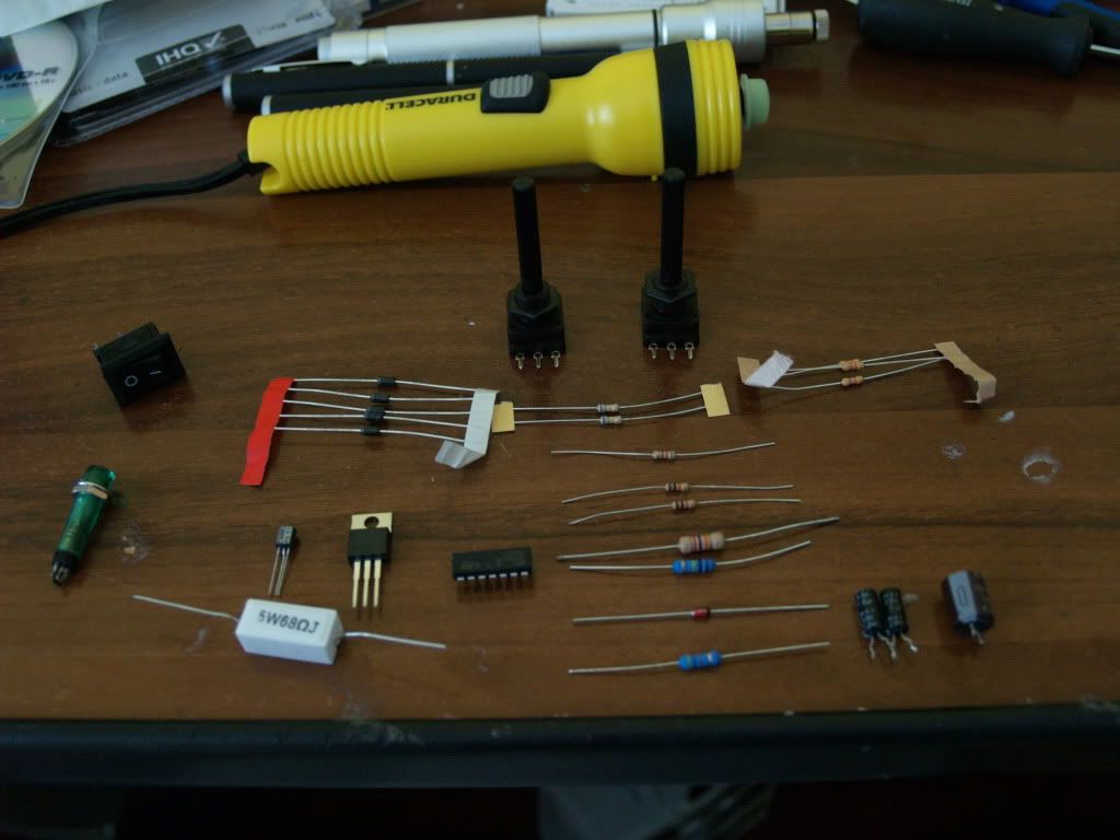
List of parts:
RESISTORS
100Ω / 0.25W R8 \
120Ω/ 5W R3 / -note that these change according to the tabel that follows
10kΩ/ 0.25W R2,R7
27kΩ/ 1W R6
47kΩ/ 0.25W R4, R5, R10
47kΩ/ 1W R11
100kΩ/ 0.5W R9
330kΩ/ 0.5W R1
500Ω POT RV1, RV2
CAPACITORS
1 uF/ 35V tantalum C1,C2
470uF/ 16V electrolyctic C3
SEMICONDUCTORS
1N4007 D1-D5
1N4148 D6,D7
10V ZENER/ 1W ZD1
BC548 Q1
LM339 IC1
TIC 106D SCR1
MISC
FUSE 1A
6 TERMINAL CONNECTOR (SCREW COUPLER)
220V INDICATOR LIGHT (WITH PRERESISTOR)
POWER CABLE
HOUSING
Now, there is a table that shows the values of R3 and R8, according to your soldering iron's power
POWER R3 R8
20W-30W 100Ω 680Ω
30W-40W 68Ω 820Ω
40W-60W 47Ω 680Ω
60W-75W 33Ω 1kΩ
75W-100W 27Ω 820Ω
100W-120W 18Ω 1.8kΩ
120W-150W 15Ω 1.5kΩ
Now, for those that are having trouble unsderstanding....
Oh yeah, also you will need a couple of lasers to let out your frustration on some innocent matches, if something goes wrong.
Now, obviously you will need a PCB, because 220V AC running through components that are connected with wires in mid air, is definetly not good.
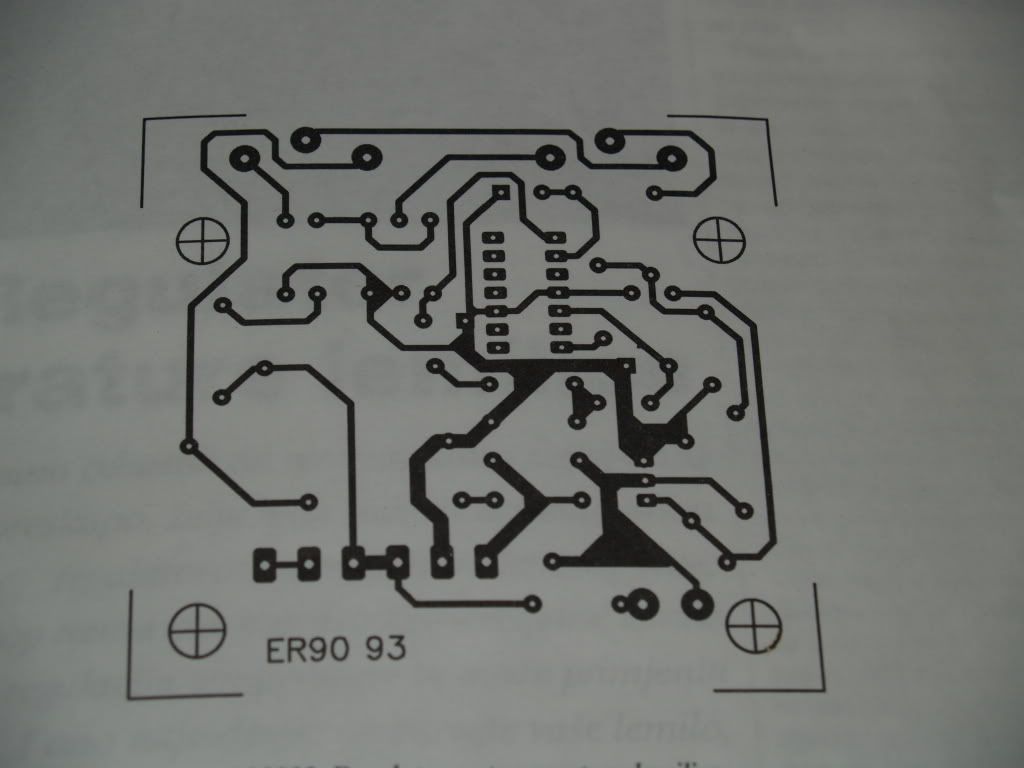
Here is my suggestion when making a PCB.
First you need a template, if you are lucky enough to be provided one. I was lucky
I am making my PCB the simplest way: Drawing the lines on PCB (directly) with waterproof marker (or sharpie) then throwing it into echant (salt acid with little bit of Hydrogen Peroxide). Everything that is under waterproof marker will stay protected, anything that is not will be eated away.
Now, grab a piece of ordinary copy paper and redraw the template, by putting it over the template and pressing it hard so oyu cann see the dark lines of the template through the paper.
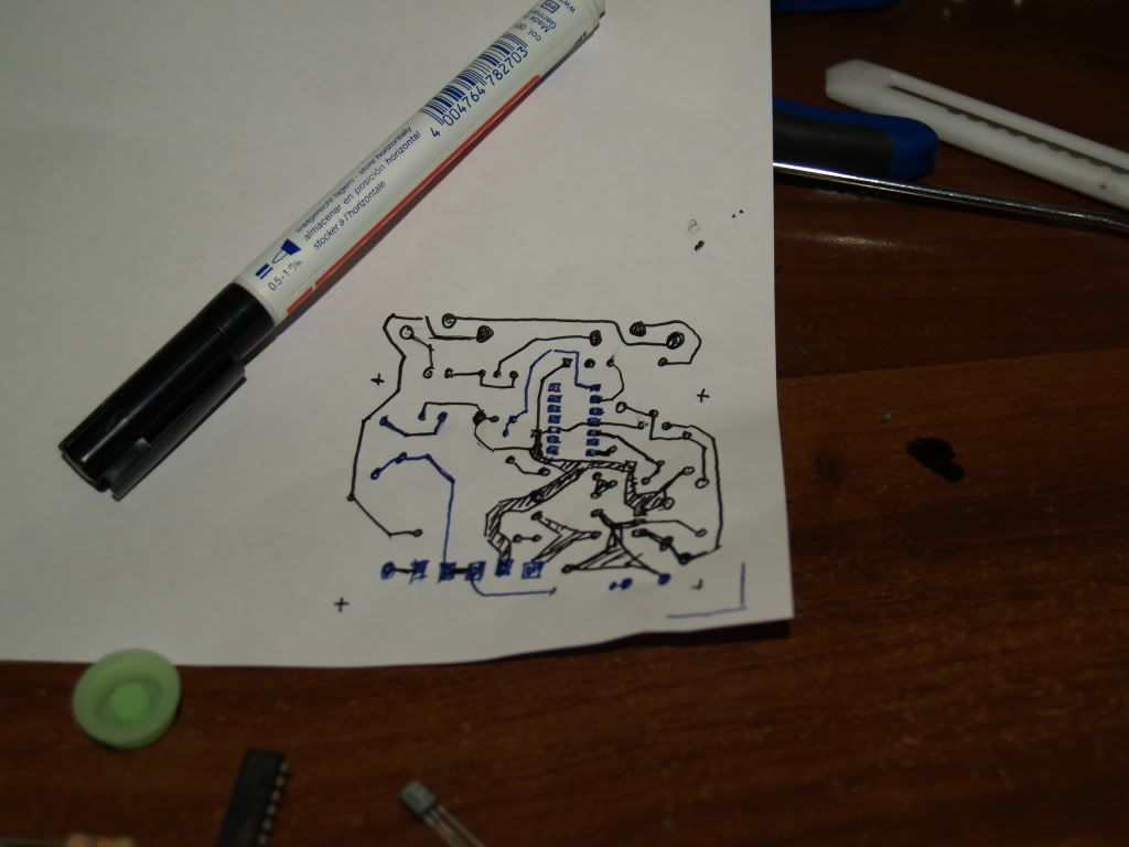
Now, the reason we have redrawn it is pretty much selfexpanatory, here:
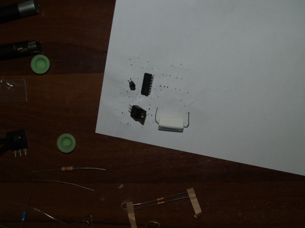
Try piercing the paper with the components, making sure everything fits, and is the right size. For instance my potenciometers were different so i had to adjust my prototype, for the proper alligning of the holes for the pots.
When you made sure the components you have will match the template (or your modified prototype), use that piece of paper, with the holes made by 'trying' out the components, do this:
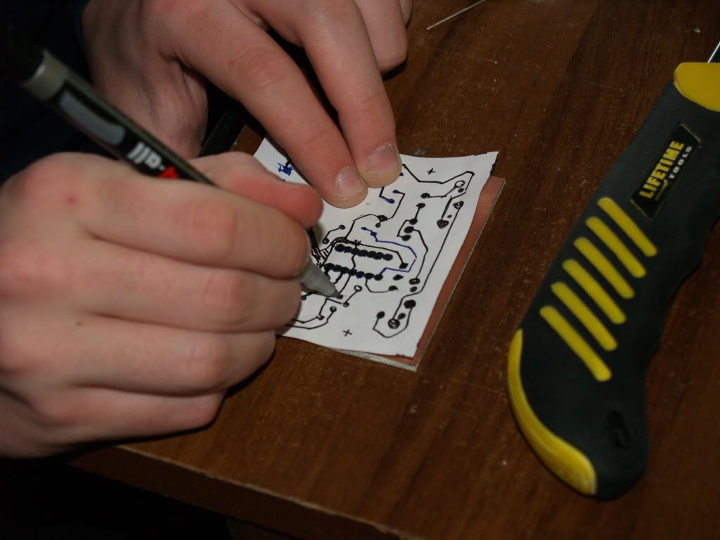
That means grabbing the anti etchant sharpie, and making the dots through the holes made on the paper. That way you ensure two things:
1) saving millions of years needed to measure templates' holes with ruler and redrawing them on PCB
2)Apsolute precision (if the template was correct)
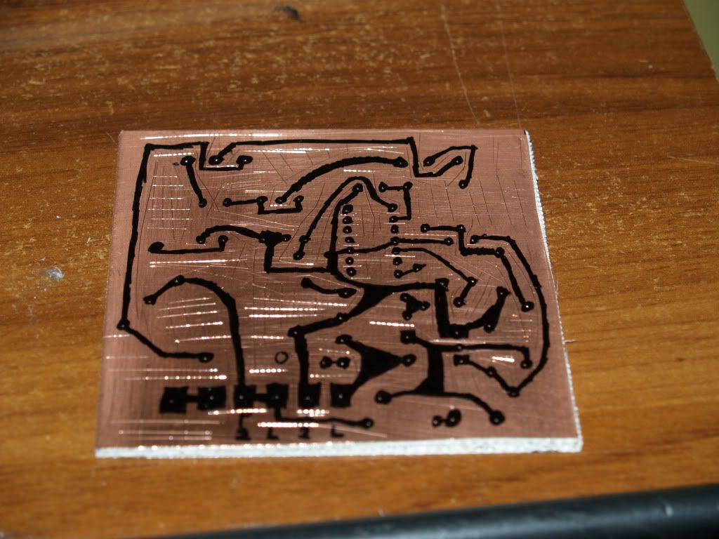
Now you will end up by something like this
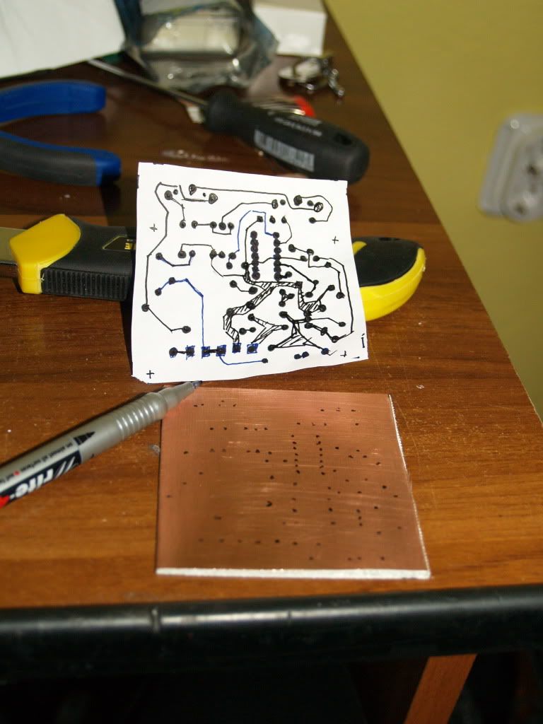
Now only thing you need to do is simply do the connecting.
Always double+triple check everything. You don't want to miss a line, or connect it to wrong pad.
Tip of advice to the people that had never done PCB before:
It is not enough to make one stroke for one connection line.
You should bold it, and repeat it 2 or 3 times, so it is pitch black, otherwise you will not get much of it.
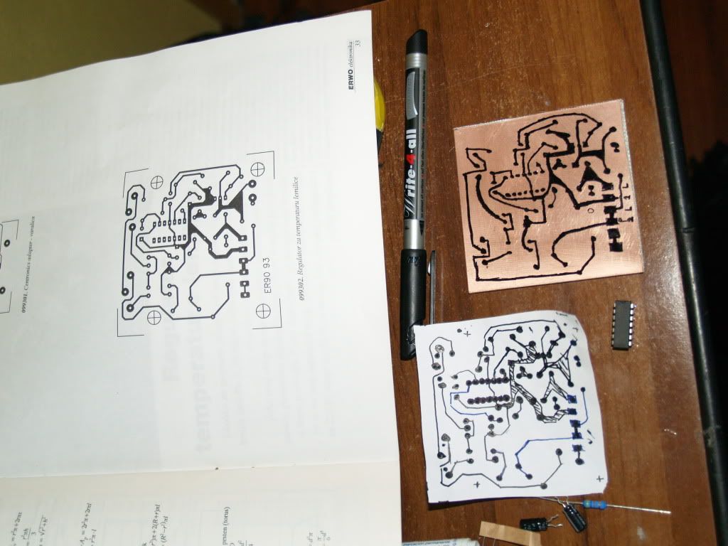
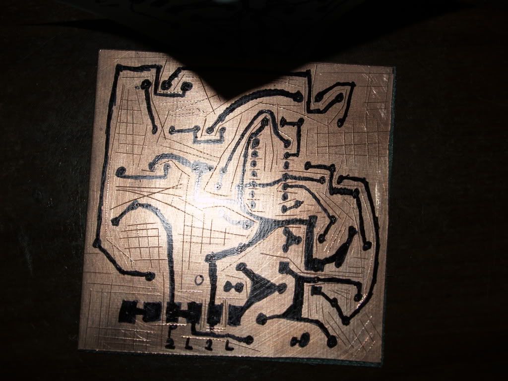
Now that you have made the drawing on the PCB, there is one very smart thing you can do: Grab a razor blade, and make a deep cut BETWEEN the connections, so you ensure that no leftover copper can make a short. The reason is that you make larger surface of the copper that will be submegrged into acid, and therefore (as small as it may seem) you will notice that the cut parts will disolve as twice as fast as the ones intact (you also scrap the possible corosive or rust layer, also making the acid's job easier). When there is are with no connections , just cut a grid over it.
You should end up with something like this:
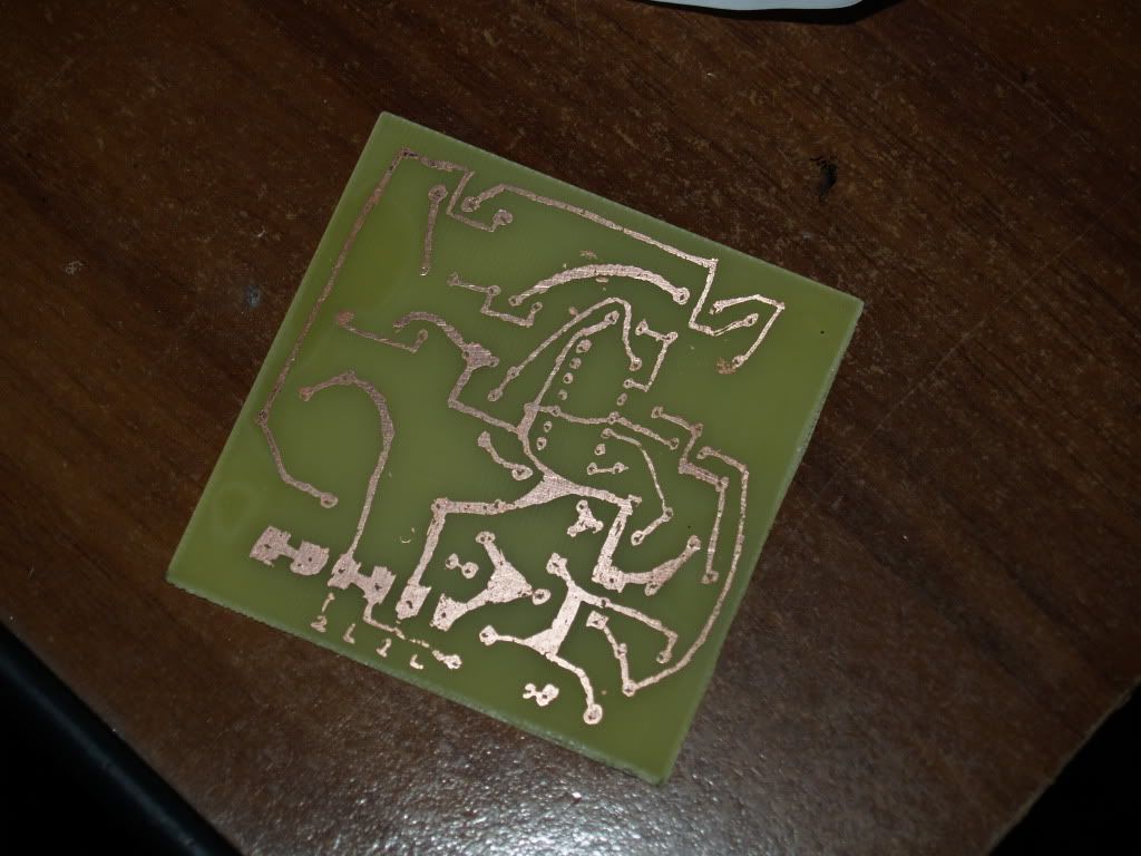
Now the only thing left to do is put it in the PLASTIC tray, and pour just enough acid to cover it. That add little bit of Peroxide. Doesn't exactly matter much if you measure it with precise scale, or eye. Just that there is some.
You should first notice change from specular shine copper, to dark matte copper color. Then over 10 minutes of so, it will fade away.
You should finally end up with your PCB (marker leftover color is washed with powder dishwahing substance, and water)
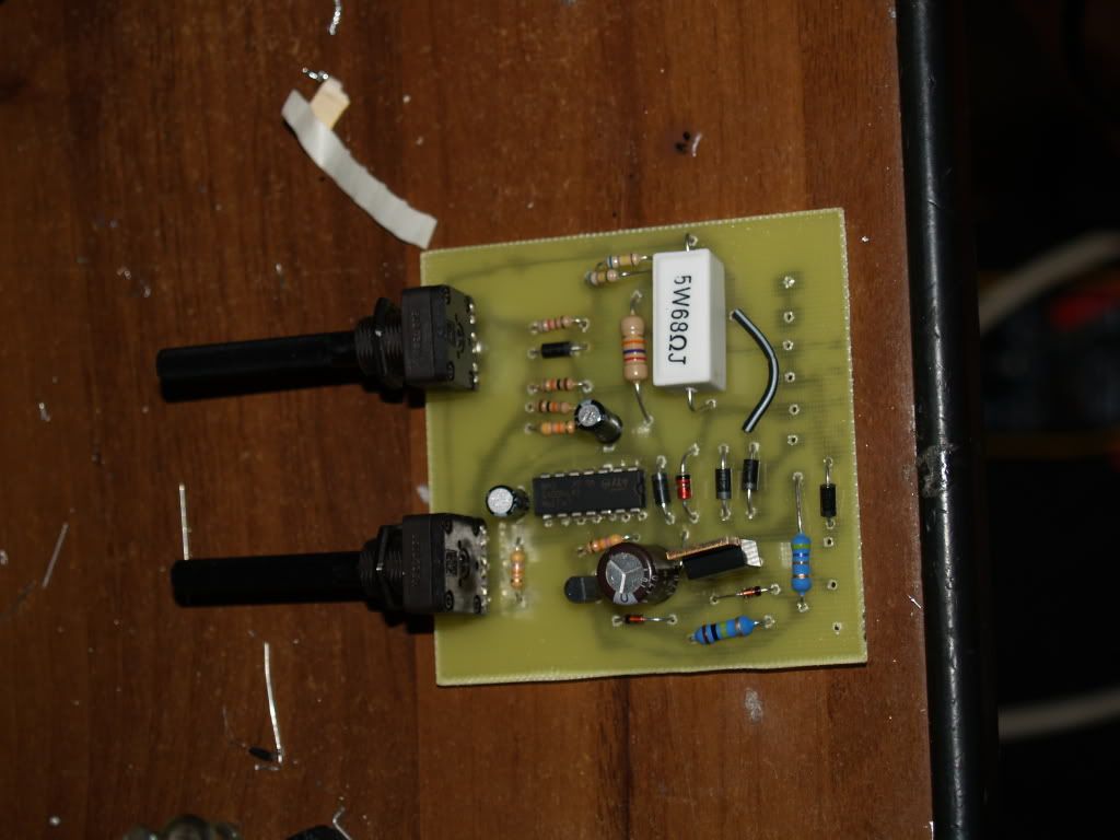
Now, only thing left to do is to solder you components on it.
You should start with you ICs first, then the smallest components, then the largest. Solder them one by one, as one is soldered it offers 'recognisable landmark' for the others, reducing the chances of misplacing the components. If it falls of as yo turn the board around to solder it, you should cross (bend) its pins, so they hold the component.
I guess I should not explain how to solder properly now do I?
Well, to end the tutorial of making a PCB, and resume the temperature regulator project, i just post embed code here (picture says thousand words)
To explain the regulator more thoroughly:
As the heater of iron is increasing the temperature, so it's resistance changes.
LM339 is comparating circuit, there fore it should compare the voltage set by pots (one is large scale, other is finetuning) to the voltage drop on the heater.
If someone is interested i will translate the entire article of the magasine, for precise explanation.
Well, that is it for now, end of PART 1 is <here>
Reason: I'm still missing 220V AC plug (so I don't have to cut the cable of soldering iron), I'm out of solder (it is holiday and a weekend), I'm out of luck today (PCB ended up pretty bad due to corosive layer not being thoroughly cleaned, as said before, ran ott of solder, and missing a project box).
PART 2 will be posted in a weeks time, that means next weekend, since I'm going to school in a city 85 km from my house, I'm in a dorm, so I cannot place my workplace there.
It will cover the placing of the 220V indicator, and firing up my makeshift soldering station, tuning the pots and (if neccesary) correction of mistakes.
NOTE: I did not have the tantalum caps of 1uF , so I used electrolyctic.
Well, till next weekend folks, have fun with the schematic and making your own soldering station for cheap
NOTE2: ALL the parts were 10$ at my local store (except PCB, acid, and soldering iron OFC).
Enjoy !
How many of you still have soldering irons for 5$ ?
How many of you wanted 100$/200$ soldering station?!
Holy shit that is a lotta hands...
Well, I have a solution for you! That is, if you are willing to put effort in it.
Like many others, I'm still stuck with 4$ soldering iron, for simple reason, I cannot afford anything better. Well I'll be damned if I ain't having my moments of luck from time to time... I will not bother you with the story of how i got hold of 1993 year magazine Erwo, in which there was a schematic... Rather interesting one.
Allow me to interpret the text that accompanies the schematic.
Soldering stations temperature is regulated from the feedback of the probe inside the tip. That is one expensive tip.
If you were to do something on that scheme, you'd encounter many problems. First, as most common thermistors and silicon diodes (used to measure the temp) are not able to withstand such high temperatures, choice falls on the more expensive and hard-to-get probes.
But even if you were to get them, problem is installing them. That alltogether represents massive change of good old soldering iron.
So how to get the feedback? Phisics science is giving us the answer right in the middle of the iron: The heater!
The heater itself is nothing more that coil resistor. That means it also has all the properties of the resistor! With the change of temperature, it changes it's resistance.
Therefore, you are spared of buying expensive probes/tips/handles.
You do not need to modify the soldering iron at all!
Now, for the schematic
List of parts:
RESISTORS
100Ω / 0.25W R8 \
120Ω/ 5W R3 / -note that these change according to the tabel that follows
10kΩ/ 0.25W R2,R7
27kΩ/ 1W R6
47kΩ/ 0.25W R4, R5, R10
47kΩ/ 1W R11
100kΩ/ 0.5W R9
330kΩ/ 0.5W R1
500Ω POT RV1, RV2
CAPACITORS
1 uF/ 35V tantalum C1,C2
470uF/ 16V electrolyctic C3
SEMICONDUCTORS
1N4007 D1-D5
1N4148 D6,D7
10V ZENER/ 1W ZD1
BC548 Q1
LM339 IC1
TIC 106D SCR1
MISC
FUSE 1A
6 TERMINAL CONNECTOR (SCREW COUPLER)
220V INDICATOR LIGHT (WITH PRERESISTOR)
POWER CABLE
HOUSING
Now, there is a table that shows the values of R3 and R8, according to your soldering iron's power
POWER R3 R8
20W-30W 100Ω 680Ω
30W-40W 68Ω 820Ω
40W-60W 47Ω 680Ω
60W-75W 33Ω 1kΩ
75W-100W 27Ω 820Ω
100W-120W 18Ω 1.8kΩ
120W-150W 15Ω 1.5kΩ
Now, for those that are having trouble unsderstanding....
Oh yeah, also you will need a couple of lasers to let out your frustration on some innocent matches, if something goes wrong.
Now, obviously you will need a PCB, because 220V AC running through components that are connected with wires in mid air, is definetly not good.
Here is my suggestion when making a PCB.
First you need a template, if you are lucky enough to be provided one. I was lucky
I am making my PCB the simplest way: Drawing the lines on PCB (directly) with waterproof marker (or sharpie) then throwing it into echant (salt acid with little bit of Hydrogen Peroxide). Everything that is under waterproof marker will stay protected, anything that is not will be eated away.
Now, grab a piece of ordinary copy paper and redraw the template, by putting it over the template and pressing it hard so oyu cann see the dark lines of the template through the paper.
Now, the reason we have redrawn it is pretty much selfexpanatory, here:
Try piercing the paper with the components, making sure everything fits, and is the right size. For instance my potenciometers were different so i had to adjust my prototype, for the proper alligning of the holes for the pots.
When you made sure the components you have will match the template (or your modified prototype), use that piece of paper, with the holes made by 'trying' out the components, do this:
That means grabbing the anti etchant sharpie, and making the dots through the holes made on the paper. That way you ensure two things:
1) saving millions of years needed to measure templates' holes with ruler and redrawing them on PCB
2)Apsolute precision (if the template was correct)
Now you will end up by something like this
Now only thing you need to do is simply do the connecting.
Always double+triple check everything. You don't want to miss a line, or connect it to wrong pad.
Tip of advice to the people that had never done PCB before:
It is not enough to make one stroke for one connection line.
You should bold it, and repeat it 2 or 3 times, so it is pitch black, otherwise you will not get much of it.
Now that you have made the drawing on the PCB, there is one very smart thing you can do: Grab a razor blade, and make a deep cut BETWEEN the connections, so you ensure that no leftover copper can make a short. The reason is that you make larger surface of the copper that will be submegrged into acid, and therefore (as small as it may seem) you will notice that the cut parts will disolve as twice as fast as the ones intact (you also scrap the possible corosive or rust layer, also making the acid's job easier). When there is are with no connections , just cut a grid over it.
You should end up with something like this:
Now the only thing left to do is put it in the PLASTIC tray, and pour just enough acid to cover it. That add little bit of Peroxide. Doesn't exactly matter much if you measure it with precise scale, or eye. Just that there is some.
You should first notice change from specular shine copper, to dark matte copper color. Then over 10 minutes of so, it will fade away.
You should finally end up with your PCB (marker leftover color is washed with powder dishwahing substance, and water)
Now, only thing left to do is to solder you components on it.
You should start with you ICs first, then the smallest components, then the largest. Solder them one by one, as one is soldered it offers 'recognisable landmark' for the others, reducing the chances of misplacing the components. If it falls of as yo turn the board around to solder it, you should cross (bend) its pins, so they hold the component.
I guess I should not explain how to solder properly now do I?
Well, to end the tutorial of making a PCB, and resume the temperature regulator project, i just post embed code here (picture says thousand words)
To explain the regulator more thoroughly:
As the heater of iron is increasing the temperature, so it's resistance changes.
LM339 is comparating circuit, there fore it should compare the voltage set by pots (one is large scale, other is finetuning) to the voltage drop on the heater.
If someone is interested i will translate the entire article of the magasine, for precise explanation.
Well, that is it for now, end of PART 1 is <here>
Reason: I'm still missing 220V AC plug (so I don't have to cut the cable of soldering iron), I'm out of solder (it is holiday and a weekend), I'm out of luck today (PCB ended up pretty bad due to corosive layer not being thoroughly cleaned, as said before, ran ott of solder, and missing a project box).
PART 2 will be posted in a weeks time, that means next weekend, since I'm going to school in a city 85 km from my house, I'm in a dorm, so I cannot place my workplace there.
It will cover the placing of the 220V indicator, and firing up my makeshift soldering station, tuning the pots and (if neccesary) correction of mistakes.
NOTE: I did not have the tantalum caps of 1uF , so I used electrolyctic.
Well, till next weekend folks, have fun with the schematic and making your own soldering station for cheap
NOTE2: ALL the parts were 10$ at my local store (except PCB, acid, and soldering iron OFC).
Enjoy !
Last edited:


